
Mastering Process Visibility: A Guide to Representing Business Rules in Visual Paradigm BPMN
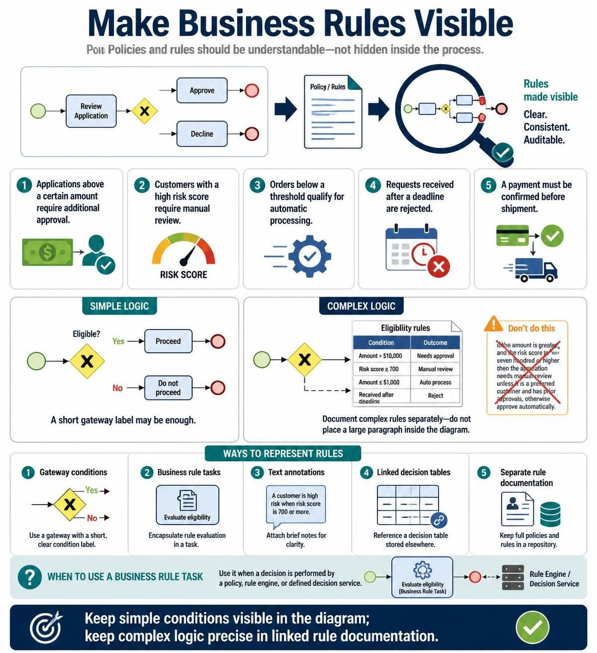
In the world of Business Process Management (BPM), clarity is king. One of the most common pitfalls in process modeling is hiding the “brain” of the operation inside the diagram, making it difficult for stakeholders to understand the logic. This tutorial explores how to make business rules visible, ensuring your processes are clear, consistent, and auditable.
We will walk through the architectural concepts of modeling decision points, distinguishing between simple and complex logic, and learning the specific best practices for using Visual Paradigm to represent these rules effectively.
The Core Challenge: Hidden Logic
Many process decisions depend on policies that are not immediately obvious from the visual flow. If a stakeholder looks at a diagram, they should understand the “what” and “how,” but the specific “when” often relies on complex rules. Hiding these rules inside large text blocks or assumptions makes the model brittle and hard to maintain.
Common Examples of Hidden Rules
Before we model, we must identify the types of rules we are dealing with. These include:
- Thresholds: “Applications above a certain amount require additional approval.”
- Risk Assessment: “Customers with a high risk score require manual review.”
- Automation Triggers: “Orders below a threshold qualify for automatic processing.”
- Temporal Constraints: “Requests received after a deadline are rejected.”
- Sequential Dependencies: “A payment must be confirmed before shipment.”
Architectural Strategies: Simple vs. Complex Logic
Visual Paradigm allows for different levels of abstraction. The key is to choose the right representation based on the complexity of the decision.
1. Simple Logic: Gateway Conditions
For straightforward “If-Then” scenarios, the best practice is to keep the logic visible directly on the diagram using a Exclusive Gateway.
When modeling this, avoid generic labels like “X”. Instead, use a short, descriptive condition label on the outgoing sequence flow or the gateway itself. This ensures that anyone reading the flowchart immediately knows the criteria for branching.
2. Complex Logic: Externalized Documentation
When logic involves multiple variables (e.g., amount, risk score, customer tier), placing a large paragraph of text inside the BPMN diagram creates clutter and reduces readability.
The “Don’t Do This” Rule: Never cram a wall of text into the diagram. Instead, use a Decision Table or a linked Business Rule Task.
Visual Paradigm excels here. You can link a gateway or a task to a separate artifact, such as a Decision Table. This keeps the process map clean (the “Simple Logic” view) while allowing you to drill down into the detailed conditions (the “Complex Logic” view) without losing context.
Five Ways to Represent Rules in BPMN
Visual Paradigm provides five distinct mechanisms to visualize rules. Here is how to apply them effectively.
1. Gateway Conditions
Use a gateway with a short, clear condition label (e.g., “Eligible?”). This is the most direct way to represent logic that doesn’t require external calculation.
2. Business Rule Tasks
Encapsulate rule evaluation in a specific task type. A Business Rule Task is appropriate when the decision is performed by a policy, a rule engine, or a defined decision service rather than a human.
3. Text Annotations
For quick clarifications, use text annotations attached to the diagram. For example, a note explaining “A customer is high risk when risk score is 700 or more” can clarify a gateway label.
4. Linked Decision Tables
Reference a decision table stored elsewhere. This is ideal for tabular data where multiple conditions (Amount, Risk Score) determine a single outcome (Needs Approval, Auto Process).
5. Separate Rule Documentation
Keep full policies and rules in a repository. This is useful for compliance audits where the full text of a regulation is needed but doesn’t fit in a process diagram.
Technical Implementation Guide
To implement these concepts in Visual Paradigm, follow this structured approach.
Step 1: Define the Decision Point
Identify where the process diverges. In BPMN, this is typically an Exclusive Gateway.
Step 2: Determine the Representation
Ask: Is this a simple condition or a complex policy?
- If Simple: Label the sequence flow directly.
- If Complex: Add a Business Rule Task or link to a Decision Table.
Step 3: Create the Rule Artifact
If using a Business Rule Task, ensure you configure the task to point to the specific rule engine or policy document. In the diagram, this looks like a specific task type with a gear icon, indicating automated or policy-based execution.
Summary: Best Practices for Auditability
To ensure your process models are robust:
- Keep Simple Conditions Visible: If a rule can be stated in a few words, put it on the diagram.
- Keep Complex Logic Precise: Move detailed logic to linked documentation or decision tables.
- Be Consistent: Ensure that the logic in the diagram matches the logic in the rule engine.
By following these architectural guidelines, you transform your BPMN diagrams from simple flowcharts into powerful, self-documenting systems.