Building robust software systems involves managing significant complexity. As systems grow, the interactions between parts become harder to visualize and control. Large-scale component modeling provides a structured way to represent these interactions. This guide explores how to approach system architecture using component diagrams effectively. We will focus on principles, strategies, and practical steps without relying on specific tools.
Understanding the Core Challenge 🧩
When a system expands beyond a single application, it enters a domain where monolithic thinking fails. Developers need to see the boundaries between different parts of the system. Component modeling serves as a bridge between high-level business goals and low-level code implementation. It allows teams to discuss structure without getting bogged down in syntax.
The primary goal is clarity. A well-designed component model reduces cognitive load. It helps stakeholders understand where data flows and where responsibilities lie. Without this clarity, technical debt accumulates rapidly. Teams struggle to onboard new members. Maintenance becomes a guessing game. Therefore, investing time in accurate modeling is essential for long-term health.
What Defines a Component? ⚙️
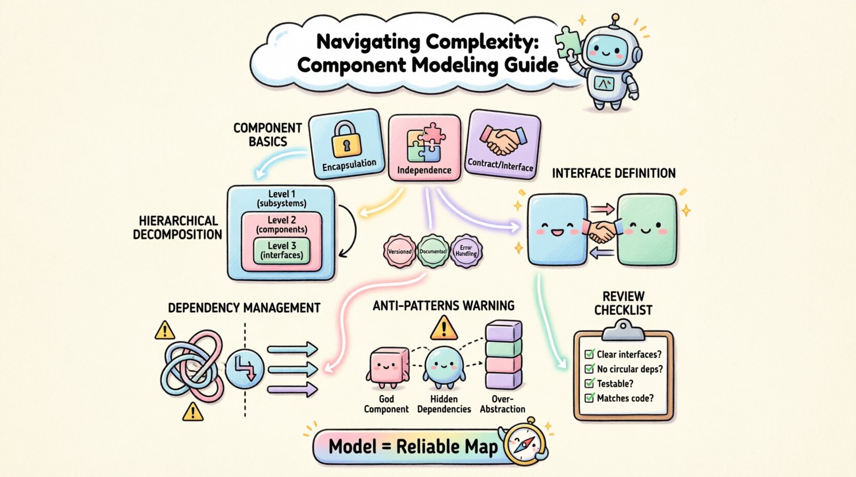
A component is a modular unit of software. It encapsulates implementation details behind a defined interface. This separation allows teams to change internal logic without affecting other parts of the system. In large-scale environments, components often represent services, libraries, or subsystems.
- Encapsulation: Internal state is hidden. Only exposed interfaces are accessible.
- Independence: Components should be deployable and replaceable independently.
- Contract: Interfaces define the contract for interaction. They act as the boundary.
Understanding these attributes is crucial. If a component leaks implementation details, coupling increases. High coupling makes changes risky. It slows down development velocity. Proper modeling ensures that boundaries are respected from the start.
Strategies for Scaling Modeling Efforts 📈
Creating a diagram for a small system is straightforward. Creating one for a large enterprise system requires discipline. You cannot fit everything on a single page. You must use hierarchy and abstraction to manage the view.
1. Hierarchical Decomposition 🔍
Break the system into layers. The top level shows major subsystems. The next level details the components within those subsystems. This approach prevents clutter. It allows readers to zoom in only when necessary.
- Level 1: Top-level subsystems (e.g., Billing, User Management, Reporting).
- Level 2: Key components within each subsystem.
- Level 3: Detailed interfaces and specific classes if needed.
This structure mirrors how teams organize their codebases. It aligns technical structure with organizational structure. This alignment reduces friction during collaboration.
2. Interface Definition 🤝
Interfaces are the most critical part of component modeling. They define how components talk to each other. In large systems, interfaces must be versioned and documented clearly. Ambiguity in interface definitions leads to integration failures.
- Define input and output types explicitly.
- Specify error handling protocols.
- Document state changes and side effects.
When interfaces are well-defined, teams can work in parallel. One team modifies a component without needing to know the internal workings of another. This decoupling is the essence of scalable architecture.
3. Managing Dependencies 🔗
Dependencies are relationships between components. In large models, dependency graphs can become tangled. You must minimize these relationships. Prefer composition over inheritance. Use dependency injection to manage connections.
Consider the direction of data flow. Dependencies should generally point towards abstractions, not concrete implementations. This pattern allows for flexibility. It enables swapping components without rewriting the entire system.
Best Practices for Component Diagrams 📝
Consistency is key. If every diagram looks different, the documentation becomes useless. Establish a standard for how components are drawn. Define rules for naming conventions. Ensure that icons and symbols mean the same thing across all diagrams.
Table 1: Modeling Standards Comparison
| Standard | Focus | Best For | Complexity |
|---|---|---|---|
| Logical View | Functional relationships | Architecture Planning | Low |
| Physical View | Deployment topology | Infrastructure Teams | Medium |
| Implementation View | Source code structure | Developers | High |
Choosing the right view depends on the audience. Executives need the logical view. Engineers need the implementation view. A single diagram rarely satisfies everyone. Create a suite of diagrams tailored to specific needs.
Table 2: Common Anti-Patterns
| Anti-Pattern | Description | Impact |
|---|---|---|
| God Component | A single component handles too many responsibilities | High coupling, hard to test |
| Hidden Dependencies | Dependencies not shown in the diagram | Integration surprises |
| Over-Abstraction | Too many layers of indirection | Performance overhead, confusion |
Avoiding these patterns requires vigilance. Regular reviews of the model help catch issues early. Encourage peer reviews of diagrams just as you would review code.
Handling Evolution and Change 🔄
Software is never static. Requirements change. Technology evolves. A component model that was perfect last year may be obsolete today. You must design for evolution. Treat the model as a living document.
Versioning the Model 📅
Just like code, the model needs version control. Track changes to interfaces. Record why changes were made. This history helps new team members understand the context. It prevents repeating past mistakes.
- Document the date of the change.
- Identify the owner of the change.
- Link the change to a specific ticket or requirement.
This audit trail builds trust. It shows that decisions were made intentionally. It reduces the fear of breaking existing functionality.
Communication Channels 💬
Models are not just for documentation. They are communication tools. Use them in design meetings. Walk through the diagram with stakeholders. Ensure everyone agrees on the structure before coding begins.
Disagreements found during modeling are cheaper than disagreements found during integration. Spend time clarifying boundaries. Resolve conflicts at the diagram level.
Technical Considerations for Implementation 🛠️
While the model is abstract, it must align with reality. The implementation must respect the boundaries defined in the diagram. If the code violates the model, the model becomes fiction.
Enforcing Boundaries 🚧
Use architectural constraints to enforce boundaries. Static analysis tools can check for dependency violations. Automated tests can verify that components do not leak interfaces. These mechanisms keep the system honest.
- Set up linting rules for import statements.
- Configure build pipelines to check architectural layers.
- Run integration tests that validate interface contracts.
These checks act as guardrails. They prevent drift. They ensure that the written model matches the running system.
Documentation Synchronization 📚
Keep documentation in sync with the code. If you update a component, update the diagram. If you change an interface, update the interface definition. Outdated documentation is worse than no documentation. It misleads readers.
Consider generating diagrams from code annotations. This ensures the model is always current. It removes the burden of manual updates. However, do not rely solely on generation. Manual review is still necessary for high-level design.
Organizational Alignment 🤝
Technology does not exist in a vacuum. Teams work together. Components map to teams. This mapping is known as Conway’s Law. The structure of the system reflects the structure of the organization.
Team Boundaries 👥
Align component boundaries with team boundaries. This reduces communication overhead. It allows teams to move faster without coordinating constantly. Each team owns their component end-to-end.
- Define clear ownership for each component.
- Establish escalation paths for cross-team issues.
- Create integration points that are stable and agreed upon.
When teams own their boundaries, they feel responsible for quality. They are less likely to break things for others. This ownership culture is vital for large-scale success.
Review and Refinement Process 🔎
Modeling is an iterative process. You will not get it right the first time. Plan for review cycles. Schedule regular sessions to look at the diagrams. Ask critical questions.
Key Review Questions ❓
- Are the interfaces clear and unambiguous?
- Are there circular dependencies?
- Can this component be tested in isolation?
- Is the deployment topology clear?
- Does this model match the current codebase?
Answering these questions helps identify gaps. It highlights areas that need more attention. It keeps the architecture relevant.
Conclusion on Structural Integrity 🏛️
Large-scale component modeling is not about drawing pretty pictures. It is about creating a reliable map for development. It reduces risk. It clarifies responsibility. It supports long-term maintainability.
By following these principles, teams can manage complexity effectively. They can build systems that grow without collapsing under their own weight. The effort invested in modeling pays dividends in stability and speed.
Remember that the model is a tool. It serves the team. It does not replace the team. Use it to facilitate discussion. Use it to align understanding. And always ensure it reflects the truth of the system.
Start with the basics. Define your components. Draw your interfaces. Check your dependencies. Repeat as needed. This disciplined approach leads to robust architecture.

