


In the landscape of software architecture, visual modeling serves as the blueprint for complex systems. However, a frequent point of ambiguity arises when distinguishing between Component Diagrams and Package Diagrams. While both serve organizational purposes within Unified Modeling Language (UML) specifications, their intent, granularity, and application differ significantly. Misinterpreting these distinctions can lead to architectural drift, where the documentation fails to reflect the actual implementation structure.
This guide provides a deep dive into the mechanics, use cases, and structural nuances of both diagram types. By clarifying these concepts, architects and developers can ensure their documentation remains a reliable source of truth throughout the software development lifecycle. 🏗️
🔍 The Core Distinction
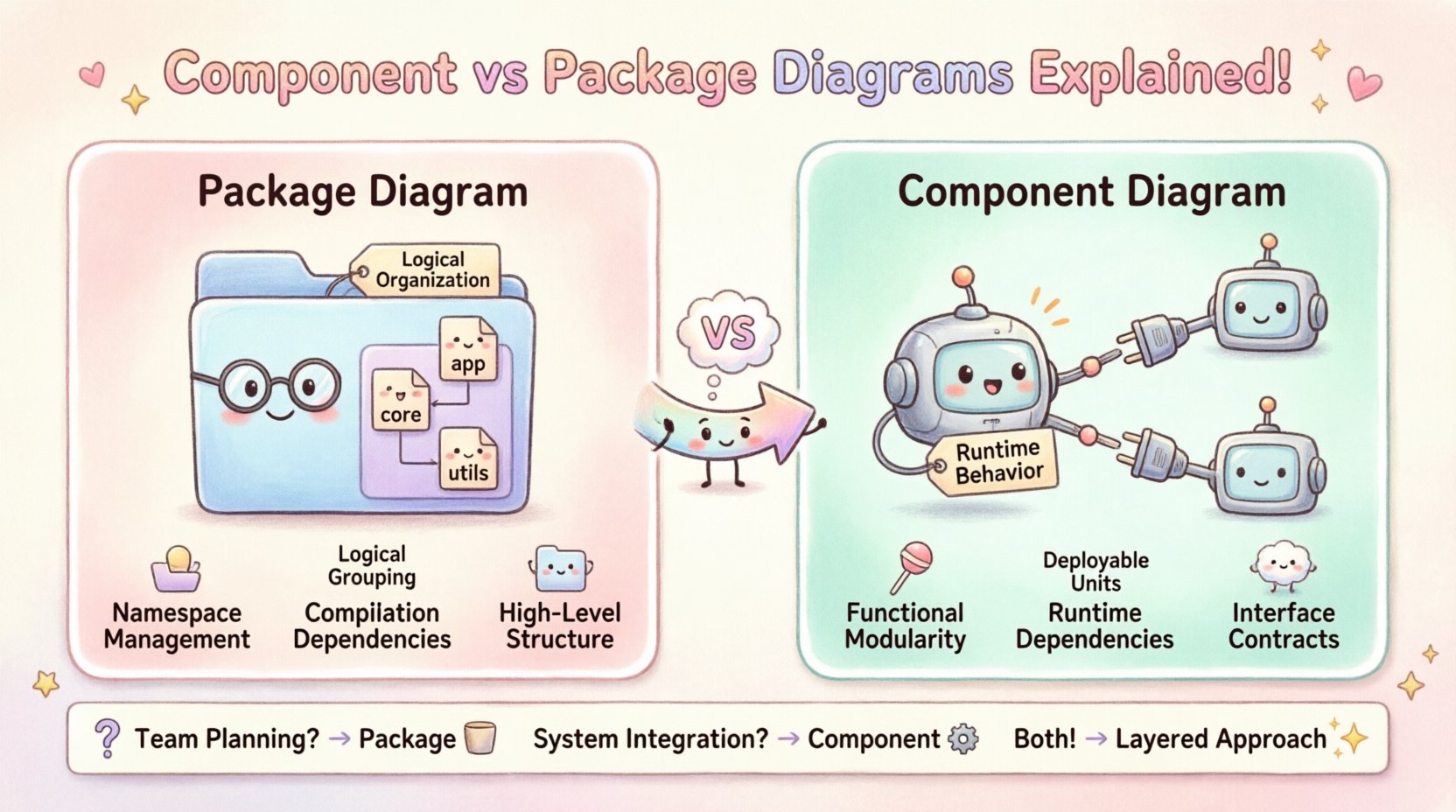
At a high level, the difference lies in the scope of abstraction. A package diagram focuses on namespace management and logical grouping. It organizes elements to prevent naming conflicts and establish dependency boundaries. A component diagram, conversely, focuses on functional modularity and runtime interaction. It details how specific units of behavior connect, communicate, and deploy.
Think of a package as a filing cabinet drawer, and a component as a specific machine part contained within that drawer. One manages organization; the other manages operation.
📦 Understanding Package Diagrams
A package is a general-purpose mechanism for organizing elements into groups. In UML, packages are often used to create namespaces. This is critical in large-scale systems where multiple developers or teams contribute code. Without packages, class names would collide, making maintenance impossible.
Primary Functions of a Package
Logical Grouping: Bundles related classes, interfaces, and other packages together based on functionality or domain.
Namespace Resolution: Prevents naming collisions by creating a hierarchy (e.g.,
com.company.module.service).Visibility Management: Controls access to elements within the package structure.
Dependency Control: Defines which packages rely on others, establishing a clear hierarchy of responsibility.
Visual Representation
In diagrams, packages are typically depicted as a folder icon. The name of the package sits at the top of the icon. Inside, you will list the elements belonging to that namespace.
When to Use a Package Diagram
During Initial Design: When defining the high-level structure of the system before implementation begins.
Module Boundaries: When delineating which teams own which parts of the codebase.
Refactoring: When reorganizing existing code to improve maintainability without changing behavior.
API Documentation: When showing how different modules expose interfaces to external systems.
A package diagram is less concerned with how the code runs and more concerned with where the code lives and who can access it. It answers the question: “How is this system logically organized?”
⚙️ Understanding Component Diagrams
A component represents a modular, deployable, and replaceable part of a system. It encapsulates implementation and exposes a set of interfaces. Unlike a package, a component has a physical or runtime existence. It implies that the unit can be compiled, deployed, or executed independently.
Primary Functions of a Component
Encapsulation: Hides internal implementation details, exposing only necessary interfaces.
Deployment: Represents a physical unit, such as a library, executable, or container.
Interface Definition: Clearly specifies required and provided interfaces (lollipop notation).
Behavior: Focuses on the functional capabilities provided to the system.
Visual Representation
Components are depicted as a rectangle with two smaller rectangles on the left side. The main body holds the component name, while the side tabs often denote specific interfaces. Arrows connecting components indicate dependencies or usage relationships.
When to Use a Component Diagram
System Integration: When showing how different subsystems interact at runtime.
Interface Contracts: When defining strict APIs between services.
Deployment Planning: When mapping components to physical hardware or servers.
Legacy Analysis: When analyzing existing binary libraries or compiled units.
A component diagram answers the question: “How does this system function and connect at runtime?”
🆚 Key Differences: A Structured Comparison
To clarify the distinctions further, the following table outlines the specific differences between the two diagram types.
Feature | Package Diagram | Component Diagram |
|---|---|---|
Focus | Logical organization and namespaces | Functional modularity and runtime behavior |
Granularity | High-level (Classes, Interfaces) | Low-level (Deployable Units, Binaries) |
Dependency Type | Compilation or logical dependency | Runtime or execution dependency |
Interface Handling | Interfaces are elements within the package | Interfaces are explicit ports (provided/required) |
Physical Existence | Abstract concept (Code structure) | Tangible unit (File, Library, Service) |
Change Frequency | Stable (Reflected in refactoring) | Frequent (Changes with deployment) |
🧠 Deep Dive: Semantic Nuances
Understanding the theoretical underpinnings helps in practical application. The confusion often stems from the fact that a package can contain components, and a component can contain classes. This nesting capability blurs the line for beginners.
The Namespace vs. The Unit
When you define a package, you are creating a container for names. If two packages define a class named User, the compiler uses the package path to distinguish them. This is purely a logical separation.
When you define a component, you are defining a unit of work. A component might contain multiple classes internally, but to the outside world, it is treated as a black box. The internal classes are hidden. This is a runtime separation.
Dependencies and Coupling
Dependencies in package diagrams are often import statements or references. They indicate that one part of the code cannot be compiled without the other.
Dependencies in component diagrams are often calls or invocations. They indicate that one service needs to send a message to another service to function correctly. This distinction is vital for microservices architecture, where network latency and availability matter.
🚦 Decision Matrix: Which Diagram to Choose?
Choosing the right diagram type depends on the audience and the stage of development. Using the wrong diagram can mislead stakeholders.
For Project Managers: Package diagrams are often preferred. They show team boundaries and module ownership without getting bogged down in technical interface details.
For Developers: Component diagrams are more useful during implementation. They clarify API contracts and integration points.
For DevOps: Component diagrams align better with deployment pipelines. They show what needs to be built, tested, and deployed.
For System Architects: A combination is often necessary. High-level packages define the structure, while detailed components define the behavior.
Scenario 1: Monolithic Application
In a traditional monolithic structure, package diagrams are often sufficient. The entire application is one deployable unit. The complexity lies in organizing the codebase to prevent spaghetti code. A package diagram effectively maps the internal structure.
Scenario 2: Microservices Architecture
In a distributed system, component diagrams become essential. Each service is an independent component. You must show how Service A connects to Service B. A package diagram would hide the network boundaries and runtime dependencies that are critical in this context.
Scenario 3: Library Development
When creating a shared library, a component diagram defines the public API. It shows what the library provides. A package diagram defines the internal structure of the library, which is less relevant to the consumer but useful for the maintainers.
🛠️ Common Pitfalls and Best Practices
Avoiding confusion requires discipline. Here are common mistakes and how to avoid them.
Pitfall: Over-Abstracting
Do not use component diagrams for every class. If a “component” is just a single class, it is better to represent it as a class in a package diagram. Components imply a level of abstraction that should not be diluted.
Pitfall: Ignoring Interfaces
In component diagrams, always define interfaces. Without interfaces, the diagram describes implementation details rather than contracts. This reduces flexibility and makes refactoring difficult.
Pitfall: Mixing Responsibilities
Do not mix package names with component names. Keep your namespaces clean. If a package is named PaymentService, the component inside should reflect that logical grouping, not a random internal class.
Best Practice: Layered Diagrams
Use a layered approach. Start with a Package Diagram to show the system’s skeleton. Then, drill down into specific packages using Component Diagrams to show detailed logic. This keeps the high-level view clean while allowing deep dives when necessary.
Best Practice: Versioning
Both diagrams should be versioned. As the software evolves, the logical structure (packages) may change, and the runtime structure (components) may change. Keeping track of these changes ensures the documentation matches the code.
🔄 Integrating Both Diagrams
It is rarely a binary choice. In mature architecture, both diagrams coexist. They serve different documents within the same ecosystem.
The Architecture Document: Might contain package diagrams to explain the logical domain model.
The Integration Guide: Might contain component diagrams to explain how to connect external systems.
The Deployment Plan: Might reference components to map to servers.
By treating them as complementary tools rather than competitors, you gain a complete picture of the system. The package diagram tells you where the code is. The component diagram tells you how the code runs.
📝 Implementation Considerations
When creating these diagrams in a tool or by hand, consider the following technical details.
Visibility Modifiers
Ensure you utilize public, private, and protected visibility modifiers. In package diagrams, this controls access between namespaces. In component diagrams, this controls access between interfaces.
Association vs. Dependency
Do not confuse associations with dependencies. An association implies a strong link (e.g., ownership). A dependency implies a usage relationship (e.g., “uses”). In component diagrams, dependencies are the primary connector. In package diagrams, associations often represent structural containment.
Documentation Standards
Maintain a standard naming convention. Use PascalCase for packages and ComponentCamelCase for components. Consistency reduces cognitive load when reading the diagrams.
🔮 Future-Proofing Your Models
Software architecture evolves. Cloud-native technologies, serverless functions, and event-driven architectures change how we view “components.”
Serverless: Functions act as components. The package structure is often hidden by the runtime.
Containers: A container image is a component. The Dockerfile defines the package structure.
API Gateways: These act as components that route requests between internal packages.
Keeping the distinction between logical grouping (package) and functional unit (component) remains valid even as the technology stack shifts. The core principles of separation of concerns and interface definition do not change.
🎯 Summary of Strategic Value
Clarity in modeling translates to clarity in execution. When developers understand the boundary between a logical namespace and a runtime unit, they make better design decisions. They know when to refactor a package and when to decompose a component.
Use package diagrams to organize your codebase. Use component diagrams to integrate your system. By applying the correct tool for the specific problem, you reduce technical debt and improve system reliability. 🚀
Remember, the goal is not to create beautiful drawings, but to create accurate models that facilitate communication and development. Stick to the definitions, respect the boundaries, and let the diagrams guide the architecture.

