


Building robust software systems relies heavily on clear communication between developers, architects, and stakeholders. The Unified Modeling Language (UML) provides a standardized way to visualize the structure and behavior of a system. Among the various diagram types, the UML Class Diagram stands out as the most critical for object-oriented design. It serves as the blueprint for the code, detailing classes, attributes, operations, and the relationships that bind them together. Without a precise diagram, the risk of architectural flaws increases significantly during implementation.
This guide provides a comprehensive checklist and framework for creating accurate, maintainable, and standard-compliant UML Class Diagrams. By following these structured steps, you ensure that the static structure of your software is documented correctly, reducing ambiguity and facilitating smoother development workflows.
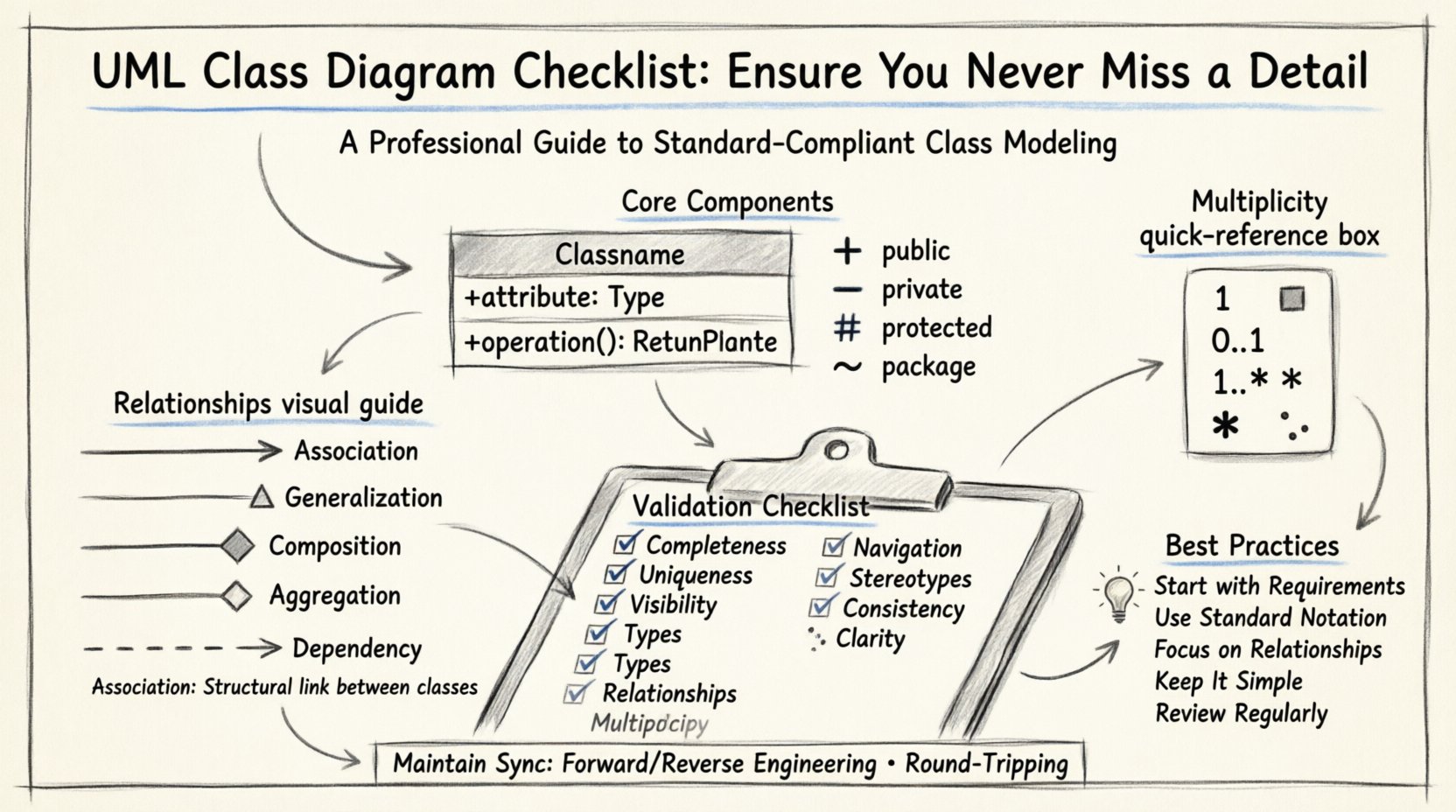
🏗️ Core Components of a Class Diagram
Before diving into relationships, it is essential to understand the fundamental building blocks. A class diagram is composed of classes, interfaces, and the connectors that define how these elements interact. Each class represents a concept, entity, or object within the domain you are modeling.
🔹 The Class Structure
A standard class rectangle is divided into three compartments. Each compartment serves a specific purpose and must be populated according to specific conventions.
- Top Compartment (Name): This section displays the name of the class. Class names should be nouns and typically follow PascalCase or TitleCase conventions. For example, CustomerOrder or PaymentProcessor.
- Middle Compartment (Attributes): This area lists the properties or state variables of the class. Each attribute defines a specific piece of data held by an instance of the class. It is crucial to specify the data type and the visibility modifier here.
- Bottom Compartment (Operations): This section details the methods or behaviors available to interact with the class. Operations define what the class can do. Like attributes, operations require visibility modifiers and return types.
If a class is abstract, it should be italicized. If it represents an interface, it should be marked with the stereotype <<interface>> or the letter I prefix depending on the notation standard used.
🔹 Attributes and Data Types
Attributes are the data held by objects. When documenting these, clarity is paramount. Every attribute must have a defined data type. Avoid vague terms like Data or Info. Instead, use precise types such as Integer, String, Boolean, or specific domain objects.
Visibility modifiers are critical for defining encapsulation rules. They dictate which parts of the system can access the attribute.
- Public (+): Accessible from any class. Use sparingly to maintain encapsulation.
- Private (-): Accessible only within the class itself. This is the default for most internal data.
- Protected (#): Accessible within the class and its subclasses. Useful for inheritance hierarchies.
- Package (/): Accessible within the same package or namespace.
🔗 Managing Relationships and Associations
Relationships define how classes interact with one another. Misinterpreting these relationships is a common source of design flaws. There are several types of associations, each with a distinct semantic meaning.
🔹 Association
An association represents a structural link between two classes. It indicates that instances of one class can be connected to instances of another. Associations are typically drawn as solid lines.
- Directionality: Use an arrowhead to show navigability. An arrow from Class A to Class B implies that A knows how to find B, but B might not know about A.
- Multiplicity: Define the number of instances involved. Common notations include 1, 0..1, 1..*, and *. This defines constraints like “one customer can place many orders” or “an order belongs to exactly one customer”.
🔹 Generalization (Inheritance)
Generalization represents an inheritance relationship. It indicates that one class is a specialized version of another. This is depicted by a solid line with a hollow triangle arrowhead pointing toward the superclass.
- Is-A Relationship: A Vehicle generalizes a Car. A Car is a Vehicle.
- Reusability: Subclasses inherit attributes and operations from the superclass, promoting code reuse.
- Polymorphism: Allows different classes to be treated through the interface of their common superclass.
🔹 Composition and Aggregation
These two types of associations describe ownership and lifecycle dependencies, often confused by practitioners.
- Composition (Filled Diamond): Represents a strong ownership relationship. The part cannot exist independently of the whole. If the whole is destroyed, the part is destroyed. Example: House composed of Rooms.
- Aggregation (Hollow Diamond): Represents a weak ownership relationship. The part can exist independently of the whole. Example: Department having Employees. If the department closes, the employee might still exist in the company.
🔹 Dependency
Dependency indicates a usage relationship. One class depends on another for its functionality, but does not own it. This is often represented by a dashed line with an open arrowhead. It implies that a change in the supplier class may affect the client class.
📊 Multiplicity and Cardinality
Multiplicity defines the quantitative constraints of a relationship. It is not enough to simply draw a line; you must specify how many objects participate in that link.
| Notation | Meaning | Example Context |
|---|---|---|
| 1 | Exactly one | A person has exactly one social security number. |
| 0..1 | Zero or one | A driver license may have a middle name (optional). |
| 1..* | One or more | A team must have at least one member. |
| * | Zero or more | A shelf can hold zero or many books. |
Ensuring multiplicity is correct prevents logical errors in database design and application logic. For instance, setting a relationship to 0..1 when it should be 1 might allow null references that crash the application.
📝 Naming Conventions and Standards
Consistency in naming is vital for readability and maintenance. A diagram with inconsistent naming conventions becomes a source of confusion rather than a tool for clarity.
🔹 Class Names
Class names should be meaningful nouns. Avoid abbreviations unless they are universally understood within the specific domain. For example, use Customer instead of Cust. Use singular forms for classes (e.g., Order rather than Orders).
🔹 Attribute and Operation Names
Use camelCase for operations and attributes to distinguish them from class names. Start with a verb for operations (e.g., calculateTotal()) and a noun for attributes (e.g., totalAmount). This distinction helps readers quickly identify whether they are looking at data or behavior.
🔹 Visibility Symbols
Always use the standard symbols for visibility to maintain professional standards.
- + for Public
- – for Private
- # for Protected
- ~ for Package/Default
🚨 Common Pitfalls and Errors
Even experienced designers make mistakes. Being aware of common errors helps in catching issues early in the design phase.
- Circular Dependencies: Avoid creating cycles where Class A depends on Class B, which depends on Class A. This complicates initialization and can lead to infinite loops.
- Missing Multiplicity: Leaving multiplicity unspecified can lead to ambiguity. Always define the constraints explicitly.
- Over-Engineering: Do not include every possible relationship. Focus on the relationships required for the current scope. Adding unnecessary complexity makes the diagram hard to read.
- Inconsistent Notation: Ensure that the same relationship type is drawn the same way throughout the diagram. Mixing association lines with dependency lines for the same logical link is confusing.
- Ignoring Interfaces: If a class implements an interface, this relationship should be explicitly shown using a dashed line with a hollow triangle. This clarifies the contract the class must fulfill.
✅ The Validation Checklist
Before finalizing a diagram, run through this validation list to ensure quality and accuracy. This section acts as a final gatekeeper for your design documentation.
- Completeness: Are all required classes from the requirements included?
- Uniqueness: Are class names unique across the diagram?
- Visibility: Is every attribute and operation marked with a visibility modifier?
- Types: Are data types specified for all attributes?
- Relationships: Are all association lines labeled with correct names?
- Multiplicity: Is every relationship line annotated with multiplicity constraints?
- Navigation: Are arrowheads placed correctly to show navigability?
- Stereotypes: Are abstract classes and interfaces clearly marked?
- Consistency: Is the notation style consistent throughout the entire diagram?
- Clarity: Is the diagram readable without excessive line crossings? (Consider using packages or layers).
🔄 Maintenance and Version Control
Software is not static. Requirements change, and the design must evolve. A UML Class Diagram is a living document that must be kept in sync with the codebase.
When code changes, the diagram should reflect those changes. If a new attribute is added to a class in the source code, the diagram must be updated to match. Conversely, if a design change is made in the diagram, the code must be adjusted accordingly. This synchronization ensures that documentation remains a reliable source of truth.
🔹 Synchronization Strategies
- Forward Engineering: Generate code from the diagram. This ensures the diagram drives the implementation.
- Reverse Engineering: Import existing code to update the diagram. This is useful for documenting legacy systems.
- Round-Tripping: Maintain bidirectional synchronization where changes in either the code or the diagram are propagated to the other.
📋 Summary of Best Practices
To summarize, creating a high-quality UML Class Diagram requires attention to detail and adherence to standards. It is not merely about drawing boxes and lines; it is about modeling the logic and constraints of your system accurately.
- Start with requirements: Ensure every class maps to a requirement or domain concept.
- Use standard notation: Stick to the official UML specifications for symbols and styles.
- Focus on relationships: The value of the diagram lies in how classes connect, not just how they look individually.
- Keep it simple: Avoid clutter. Use packages or subsystems to group related classes.
- Review regularly: Schedule design reviews to validate the diagram against current development progress.
By rigorously applying this checklist and maintaining a disciplined approach to design documentation, you create a foundation for software that is easier to understand, maintain, and extend. The effort invested in a precise class diagram pays dividends throughout the entire lifecycle of the project.

