Software architecture is the backbone of any scalable system. Among the various tools available to visualize this structure, component diagrams remain a staple in the architect’s toolkit. They are intended to provide a clear map of how different parts of a system interact, abstracting away implementation details to show functionality. However, a significant gap often exists between the theoretical utility of these diagrams and their actual usage in production environments. Many teams find themselves staring at outdated charts that no longer reflect the code running in the cluster.
When a component diagram fails, it does more than just confuse new developers. It erodes trust in documentation, leads to architectural drift, and slows down decision-making processes. This article delves deep into the mechanics of why these models break down, the tangible costs associated with that failure, and actionable strategies to restore their value without succumbing to documentation bloat.
The Promise vs. The Reality 🤥
On paper, a component diagram should serve as a single source of truth. It represents the modular breakdown of a system, highlighting interfaces, ports, and the dependencies between functional units. In an ideal scenario, this diagram is the first thing an engineer looks at to understand the boundaries of a service or a module. It answers critical questions: What does this piece do? What does it need to function? What does it expose to the outside world?
In reality, however, the static nature of these diagrams clashes with the dynamic nature of modern development. Code evolves rapidly. Microservices are split, merged, or rewritten. Interfaces change. When the diagram is treated as a static artifact rather than a living document, it quickly becomes a liability. The promise of clarity turns into a source of noise.
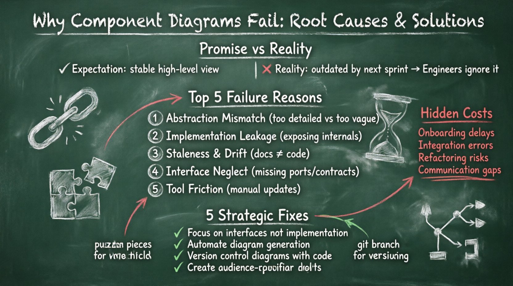
- The Expectation: A high-level view that remains stable over time.
- The Reality: A snapshot that is outdated by the next sprint.
- The Consequence: Engineers ignore the diagram entirely.
Top 5 Reasons Component Diagrams Break Down 🔍
Understanding the failure modes is the first step toward fixing them. These issues are rarely accidental; they are usually symptoms of process gaps or misaligned expectations. Below are the primary drivers behind diagram failure.
1. Abstraction Mismatch
One of the most common errors is creating diagrams that are either too abstract or too detailed. If a diagram attempts to show every single class and variable, it loses the purpose of a component view. Conversely, if it groups too much functionality into a single block, it becomes useless for understanding specific integration points. The right level of abstraction depends heavily on the audience. A deployment diagram for operations requires a different view than a design diagram for developers.
2. Implementation Leakage
Component diagrams are designed to hide implementation details. When a diagram exposes internal data structures, database schemas, or specific library dependencies, it violates the principle of encapsulation. This leakage creates tight coupling in the documentation that does not exist in the code. If the internal logic changes, the diagram must change, leading to high maintenance overhead.
3. Staleness and Drift
Software is iterative. The codebase changes daily. If the diagram update process is decoupled from the code commit process, the diagram becomes a historical artifact rather than a current reference. This drift is often exacerbated when documentation is viewed as a separate task from coding. Developers prioritize feature delivery over updating their visual models.
4. Interface Neglect
Components interact through interfaces. A diagram that focuses on the component box but ignores the ports and provided/required interfaces fails to communicate the actual contract of the system. Without clear interface definitions, the diagram cannot effectively guide integration efforts. It becomes a drawing of boxes rather than a map of data flow.
5. Tool-Driven Constraints
Using modeling tools that do not integrate well with the development workflow creates friction. If creating or updating a diagram requires exporting code, manually drawing shapes, and importing them back, the process becomes tedious. Tools that enforce rigid structures often force users to oversimplify complex realities, resulting in diagrams that look clean but lack accuracy.
The Hidden Cost of Poor Modeling 💸
The impact of a failing component diagram extends beyond the document itself. It affects the velocity and quality of the entire engineering organization. When architects rely on outdated models, technical debt accumulates silently.
- Onboarding Friction: New hires spend weeks deciphering the system because the map is wrong. This delays time-to-productivity.
- Integration Errors: Developers build against incorrect assumptions about what a service provides, leading to runtime failures.
- Refactoring Blindspots: Without accurate dependency maps, refactoring one component can break others unexpectedly.
- Communication Breakdowns: Architects and developers speak different languages if the diagram does not reflect the code.
These costs compound over time. A system that was once maintainable becomes a legacy monolith simply because the documentation failed to guide its evolution.
Strategic Fixes for Sustainable Documentation 🛠️
Fixing component diagrams requires a shift in mindset. It is not about drawing better pictures; it is about aligning documentation with the software delivery lifecycle. The goal is to reduce the gap between the model and the reality.
1. Focus on Interfaces, Not Implementation
Shift the emphasis of your diagrams to the contracts. Clearly define the services, APIs, and data streams that components exchange. Use standard notation for provided and required interfaces. This ensures that the diagram remains valid even when the internal logic of a component is rewritten, as long as the interface remains stable.
2. Automate Where Possible
Manual diagramming is a bottleneck. Explore approaches where diagrams are generated from source code or configuration files. While this does not solve every semantic issue, it ensures that the structural elements (classes, modules, services) are always up to date. This reduces the maintenance burden significantly.
3. Version Control Your Models
Treat diagrams as code. Store them in the same repository as the source code. Enable pull requests for diagram changes. This creates an audit trail and forces a review process. If a component changes, the diagram should be part of the change request, ensuring that the documentation is updated alongside the code.
4. Define Audience and Scope
Stop trying to draw one diagram for everyone. Create layered documentation. High-level architecture diagrams for stakeholders, component diagrams for developers, and deployment diagrams for operations. Each layer should answer specific questions and contain only the information relevant to that role.
5. Regular Audits
Schedule periodic reviews of your architectural documentation. Mark them as part of the sprint planning or release cycle. If a diagram is flagged as stale, it must be updated before the release is approved. This institutionalizes the maintenance process.
Comparing Pitfalls to Solutions
The following table summarizes the common failure points and their corresponding remediation strategies.
| Pitfall | Consequence | Mitigation Strategy |
|---|---|---|
| Implementation Leakage | High maintenance, tight coupling | Focus on ports and interfaces only. |
| Staleness | Misleading information, trust loss | Store in code repo, automate generation. |
| Abstraction Mismatch | Confusion, lack of utility | Define audience-specific views. |
| Tool Friction | Low adoption, manual errors | Choose tools that integrate with workflow. |
| Interface Neglect | Integration failures | Explicitly model data contracts. |
When to Use (and When to Skip) 🤷
Not every project requires a detailed component diagram. Understanding when to apply this tool is as important as knowing how to create it. For large-scale distributed systems, component diagrams are essential for managing complexity. They help teams understand boundaries and ownership.
However, for small internal tools or proof-of-concept projects, the overhead may outweigh the benefits. In these cases, code comments or simple README files may suffice. The key is to evaluate the cost of maintaining the diagram against the value it provides to the team.
- Use Component Diagrams When:
- System complexity is high.
- Multiple teams are working on different parts.
- Integration points are complex.
- Onboarding new engineers is frequent.
- Consider Alternatives When:
- Project scope is small or temporary.
- Team size is minimal.
- Code is self-documenting and simple.
Maintaining Diagram Health Over Time 🔄
Maintenance is the ongoing challenge. A diagram that is good today can be obsolete tomorrow. To sustain health, you need a feedback loop. This involves monitoring how often the diagram is referenced and how often it is corrected by developers.
If developers consistently ignore the diagram, it is likely outdated or irrelevant. If they frequently report errors, the maintenance process is too slow. Regular feedback from the engineering team should drive updates to the documentation standards. This keeps the documentation aligned with the culture of the organization.
A Practical Checklist for Architects ✅
Before finalizing a component diagram, run through this checklist to ensure it meets the standards for utility and accuracy.
- Clarity: Is the diagram readable without a legend?
- Accuracy: Does it match the current codebase?
- Completeness: Are all critical interfaces and dependencies shown?
- Consistency: Are naming conventions uniform across the system?
- Versioning: Is the diagram versioned alongside the code?
- Accessibility: Can the team access the diagram easily?
- Relevance: Does it answer the intended questions for the audience?
By adhering to these principles, teams can transform component diagrams from forgotten artifacts into vital navigation tools. The goal is not perfection, but utility. A diagram that is slightly outdated but accessible is often more valuable than a perfect one that no one can find.
Ultimately, the success of your architectural documentation depends on the discipline of the team. It requires a commitment to keeping the model in sync with the machine. When that alignment is achieved, the system becomes more resilient, and the path forward becomes clearer for everyone involved.
Final Thoughts on Architectural Integrity 🏗️
The failure of component diagrams is rarely a failure of the drawing itself. It is a failure of the process surrounding it. By addressing the root causes—abstraction, maintenance, and integration—you can build a documentation strategy that supports rather than hinders development. Focus on the interfaces, automate the updates, and treat the diagrams as code. This approach ensures that your architecture remains visible, understandable, and useful throughout the lifecycle of the software.

