Understanding the architecture of software is fundamental to building robust, maintainable systems. One of the most powerful tools available to visualize this structure is the UML Class Diagram. These diagrams provide a static view of a system, detailing its classes, attributes, methods, and the relationships between them. Whether you are designing a new application from the ground up or analyzing legacy code, mastering this notation ensures clarity and precision.
This guide explores every aspect of creating effective class diagrams. We will move from basic definitions to complex relationships, ensuring you have a solid foundation in object-oriented design principles. Let us begin the journey into the structure of software.
1. What is a UML Class Diagram? 🤔
The Unified Modeling Language (UML) serves as a standard for visualizing system designs. Among the various diagram types available, the Class Diagram is the most widely used for object-oriented programming. It represents the system’s static structure.
Unlike a Sequence Diagram, which focuses on dynamic behavior over time, a Class Diagram focuses on the what rather than the how. It answers questions such as:
- What objects exist in the system?
- What data do these objects hold?
- How do these objects interact with one another?
- What operations can be performed on these objects?
By mapping these elements, developers and stakeholders can agree on a blueprint before writing a single line of code. This reduces ambiguity and prevents costly architectural changes later in the development lifecycle.
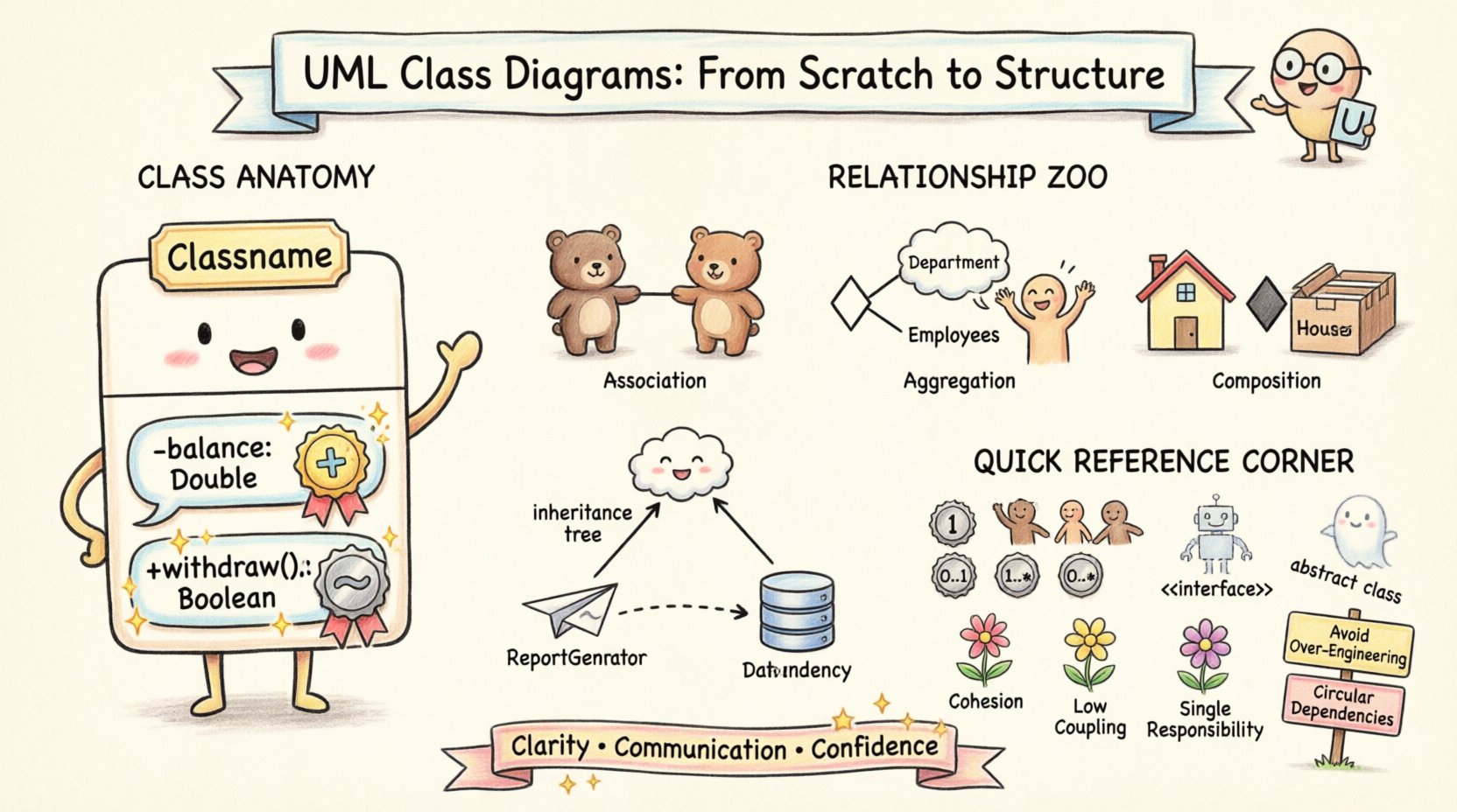
2. The Anatomy of a Class 🏗️
At the heart of a class diagram is the class itself. A class acts as a blueprint or template for creating objects. In a diagram, a class is typically represented as a rectangle divided into three compartments.
2.1. Class Name Compartment
The top section contains the name of the class. This should be a noun, representing the entity being modeled. Naming conventions usually follow PascalCase (e.g., CustomerOrder) or camelCase, depending on the project standards.
- Abstract Classes: If a class is abstract (cannot be instantiated directly), the name is often italicized.
- Static Classes: Some modeling standards underline the name to indicate static members.
2.2. Attributes Compartment
The middle section lists the attributes (variables or properties) of the class. These define the state of the object.
Attributes are typically listed with their visibility symbol, type, and name. For example:
- balance: Double+ userName: String
Each attribute describes a specific piece of data the class manages. It is crucial to define the data type clearly to ensure type safety across the system.
2.3. Methods Compartment
The bottom section contains the operations (methods or functions) that the class exposes. These define the behavior.
Similar to attributes, methods include visibility, name, and parameter types. An example might look like this:
+ withdraw(amount: Double): Boolean- validateUser(): Boolean
Methods encapsulate the logic required to manipulate the attributes or interact with other classes.
3. Visibility Modifiers 🔒
Encapsulation is a core tenet of object-oriented design. It dictates which parts of a class are accessible from the outside. In UML, this is denoted by specific symbols placed before the attribute or method name.
| Symbol | Visibility | Description |
|---|---|---|
+ |
Public | Accessible from any other class. This is the default interface for interaction. |
- |
Private | Accessible only within the class itself. Data is hidden from external view. |
# |
Protected | Accessible within the class and its subclasses (children). |
~ |
Package | Accessible within the same package or namespace. |
Choosing the correct visibility is critical for security and maintainability. Overusing public access can lead to tight coupling, while overusing private access can make testing and extension difficult.
4. Relationships Between Classes 🔗
A single class rarely exists in isolation. The true power of a class diagram lies in defining how classes connect. These relationships describe the structural dependencies between entities.
4.1. Association
Association represents a structural relationship where objects are connected. It is depicted by a solid line connecting two classes. By default, associations are bidirectional, meaning both classes know about each other.
Key points about association:
- It is a general term for any link between classes.
- It can be labeled to describe the nature of the link (e.g., “employs”, “manages”).
- It implies that one object holds a reference to another.
4.2. Aggregation
Aggregation is a specialized form of association representing a whole-part relationship. However, the part can exist independently of the whole.
Visual representation: A solid line with a hollow diamond at the end of the “whole” class.
Example: A Department aggregates Employees. If the department is dissolved, the employees still exist. They are not destroyed with the department.
4.3. Composition
Composition is a stronger form of aggregation. It also represents a whole-part relationship, but the part cannot exist without the whole.
Visual representation: A solid line with a filled diamond at the end of the “whole” class.
Example: A House is composed of Rooms. If the house is demolished, the rooms cease to exist as part of that structure. The lifecycle of the part is bound to the whole.
4.4. Generalization (Inheritance)
Generalization describes an is-a relationship. It allows a subclass to inherit attributes and methods from a superclass.
Visual representation: A solid line with a hollow triangle pointing to the superclass.
- Subclass: The more specific class (e.g.,
Employee). - Superclass: The general class (e.g.,
Person).
This relationship promotes code reuse and establishes a clear hierarchy within the system.
4.5. Dependency
Dependency is a weaker relationship indicating that one class uses another, but not necessarily holds a reference to it. It is often temporary, such as when a method parameter is passed.
Visual representation: A dashed line with an open arrow pointing to the used class.
Example: A ReportGenerator class might depend on a DatabaseConnection class to fetch data for a report. If the connection changes, the generator might need to change, but it does not own the connection.
5. Multiplicity and Cardinality 📊
Relationships are rarely one-to-one. Multiplicity defines how many instances of one class relate to how many instances of another. This is a critical detail for database schema design and logic implementation.
| Notation | Meaning |
|---|---|
1 |
Exactly one |
0..1 |
Zero or one |
1..* |
One or more (at least one) |
0..* |
Zero or more (any number) |
3..5 |
Between 3 and 5 instances |
Consider a Customer and Order relationship:
- A
Customercan place0..*orders (a customer may have no orders). - An
Ordermust belong to1customer (an order cannot exist without a customer).
Defining these constraints correctly prevents logical errors in the application code.
6. Interfaces and Abstract Classes 🧩
Not all classes are designed to be instantiated. Sometimes, we need to define contracts that other classes must follow.
6.1. Interfaces
An interface defines a set of operations that a class must implement, without providing the implementation details itself.
Visual representation: A rectangle with the stereotype <<interface>> above the name.
- Interfaces contain only method signatures.
- Multiple classes can implement the same interface.
- They allow for polymorphism and loose coupling.
6.2. Abstract Classes
An abstract class can contain both abstract methods (no body) and concrete methods (with body). It serves as a base class for other classes.
- Names are often italicized.
- They can hold state (attributes).
- Only one abstract class can be inherited per class.
Using interfaces and abstract classes allows you to design flexible systems where the implementation can change without affecting the callers.
7. Design Principles in Diagramming 🧠
Creating a diagram is not just about drawing boxes and lines; it is about applying design principles to ensure the system remains healthy over time.
- Cohesion: A class should have a single, well-defined purpose. If a class handles user authentication, file storage, and email sending, it lacks cohesion.
- Coupling: Minimize dependencies between classes. High coupling makes the system rigid and hard to test. Use interfaces to reduce direct dependencies.
- Single Responsibility: Each class should be responsible for one part of the system’s functionality.
- Open/Closed: Classes should be open for extension but closed for modification. Design interfaces that allow new features to be added without changing existing code.
8. Common Pitfalls to Avoid ⚠️
Even experienced architects make mistakes when modeling systems. Being aware of common errors can save significant time during the coding phase.
8.1. Over-Engineering
It is tempting to create deep hierarchies and complex relationships to satisfy theoretical purity. In practice, simplicity often wins. Avoid creating inheritance chains that are too deep (more than 3 or 4 levels) unless absolutely necessary.
8.2. Missing Multiplicity
Leaving multiplicity undefined forces developers to make assumptions. This can lead to bugs where null pointers occur or unexpected data structures are created.
8.3. Circular Dependencies
A situation where Class A depends on Class B, and Class B depends on Class A, can cause compilation errors or logical loops. Use interfaces or mediator patterns to break these cycles.
8.4. Ignoring Naming Conventions
A diagram with vague names like Class1 or Handler is useless. Names should be descriptive and follow the project’s standard guidelines.
9. From Code to Diagram and Vice Versa 🔄
The lifecycle of a class diagram is iterative. It is not a one-time task.
9.1. Forward Engineering
Start with the diagram and generate code. This is common in new projects where the design is finalized before implementation. Tools can parse the UML model and scaffold the initial class structure.
9.2. Reverse Engineering
Start with existing code and generate the diagram. This is essential when dealing with legacy systems. It helps visualize the current state of the codebase and identify areas that need refactoring.
10. Conclusion on Structure 🏁
The UML Class Diagram is more than just a drawing; it is a communication tool. It bridges the gap between technical requirements and implementation details. By understanding the anatomy of classes, the nuances of relationships, and the importance of design principles, you can create systems that are robust and scalable.
Remember that a diagram is a living document. As requirements change, the diagram should evolve to reflect the new reality. Consistency in notation and clear documentation ensure that anyone on the team can understand the architecture at a glance. Focus on clarity over complexity, and always prioritize the needs of the maintainers over the convenience of the initial design.
With these foundations, you are ready to model complex systems with confidence. Apply these concepts to your next project and observe how the clarity improves the development process.

