Designing robust software systems requires more than just writing code; it requires a blueprint. The Unified Modeling Language (UML) provides this blueprint, and within that language, the Class Diagram stands as the most critical structural tool. It captures the static structure of a system by defining classes, their attributes, operations, and the relationships among objects. However, drawing a diagram is only the beginning. The true value lies in applying established UML class diagram patterns. These patterns offer reusable solutions to common modeling problems, ensuring that your design remains maintainable, scalable, and clear to all stakeholders.
This guide explores the essential patterns used in object-oriented design. We will examine how to structure inheritance, manage relationships, and implement structural constraints without relying on specific tools. By understanding these patterns, you can create diagrams that communicate complex logic with precision and authority.
Understanding UML Class Diagram Fundamentals 📐
Before diving into specific patterns, it is necessary to establish a firm grasp of the building blocks. A class diagram represents a snapshot of the system at a specific point in time. Each rectangle represents a class, which is divided into three compartments:
- Name: The identifier of the class, typically capitalized.
- Attributes: The data properties stored within the class instance.
- Operations: The methods or functions the class can perform.
Visibility modifiers are crucial for defining how these elements interact:
- Public (+): Accessible from any other class.
- Private (-): Accessible only within the class itself.
- Protected (#): Accessible within the class and its subclasses.
- Package (~): Accessible within the same package or namespace.
Additionally, attributes and operations can be static or instance-based. Static members belong to the class itself rather than a specific object. In a diagram, static members are typically underlined. This foundational knowledge is the prerequisite for applying complex patterns effectively.
Inheritance and Generalization Patterns 🔗
Inheritance allows a new class to derive properties and behaviors from an existing class. This promotes code reuse and establishes a semantic hierarchy. In UML, this is represented by a solid line with a hollow triangle arrow pointing toward the superclass.
Generalization Patterns
The Generalization pattern is the backbone of hierarchical design. It answers the question: “Is this class a specialized version of that class?”
- Single Inheritance: A class inherits from only one parent. This is the most common pattern in many object-oriented languages. It keeps the hierarchy flat and easier to navigate.
- Multiple Inheritance: A class inherits from multiple parents. While powerful, this can lead to the “Diamond Problem” where ambiguity arises regarding which parent’s method to execute. In UML, this is shown with multiple solid lines ending in hollow triangles at the child class.
- Abstract Classes: These classes cannot be instantiated directly. They serve as a template for other classes. In the diagram, the class name is italicized. Abstract methods are also italicized.
When to Use Inheritance
Use inheritance when there is a clear “is-a” relationship. For example, a Square is a Rectangle. Avoid using inheritance for “has-a” relationships, as this violates the principle of composition over inheritance.
Relationship Patterns: Association, Aggregation, Composition 🧩
Relationships define how classes interact with one another. Distinguishing between Association, Aggregation, and Composition is vital for accurate modeling. These patterns define the lifecycle and ownership of the objects involved.
Association
An Association represents a structural relationship between two classes. It implies that objects of one class are aware of objects of another class. This is the most basic relationship.
- Representation: A solid line connecting two classes.
- Role Names: Labels on the line describe the relationship from the perspective of each class.
- Multiplicity: Numbers or ranges (e.g., 0..*, 1..1) indicate how many instances can be linked.
Aggregation vs. Composition
Both Aggregation and Composition are specialized forms of association, representing a whole-part relationship. The key difference lies in ownership and lifecycle.
| Feature | Aggregation | Composition |
|---|---|---|
| Ownership | Weak ownership | Strong ownership |
| Lifecycle | Part can exist without the Whole | Part cannot exist without the Whole |
| UML Symbol | Hollow diamond | Filled diamond |
| Example | Department and Professors | House and Rooms |
Aggregation: Imagine a University and its Students. If the University closes, the Students still exist. They are associated, but not owned. The hollow diamond sits on the “Whole” side of the line.
Composition: Consider a Car and its Engine. If the Car is destroyed, the Engine is no longer a functional part of that specific Car instance. The lifecycle is tied. The filled diamond sits on the “Whole” side.
Creational Patterns in Static Contexts 🛠️
While many creational patterns are behavioral, they have structural representations in Class Diagrams, particularly involving static methods and attributes. These patterns manage how objects are created.
Singleton Pattern
The Singleton pattern ensures that a class has only one instance and provides a global point of access to it. This is common for configuration managers or database connections.
- Structure: The constructor is private to prevent instantiation from outside.
- Access: A static method, typically named
getInstance(), returns the single instance. - Diagram Representation: The class name is underlined to indicate static members. The attribute holding the instance is static.
When drawing this, ensure the attribute is marked as static (underlined) and the method is also static. This visually communicates that the state belongs to the class, not an object.
Factory Method Pattern
This pattern defines an interface for creating an object, but lets subclasses decide which class to instantiate. It allows a class to delegate instantiation logic to its subclasses.
- Creator: An abstract class or interface declaring the factory method.
- Concrete Creator: Implements the factory method to return an instance of a Concrete Product.
- Product: The interface or class being created.
In a diagram, you will see a Creator class with a method returning the Product interface. This decouples the client code from the concrete classes, making the system more flexible.
Structural Patterns and Interfaces 🛡️
Structural patterns focus on how classes are composed to form larger structures. Interfaces play a massive role here, defining contracts without implementation details.
Interface Implementation
An Interface defines a set of operations that a class must implement. It is a way to enforce a contract. In UML, this is shown with a dashed line and a hollow triangle pointing to the interface.
- Separation of Concern: Interfaces allow you to separate the “what” from the “how”.
- Polymorphism: Multiple classes can implement the same interface, allowing them to be used interchangeably.
- Diagramming: The interface is often shown as a separate box with the name stereotyped as <<Interface>>. The implementation line connects the class to this box.
Dependency Injection
Dependency Injection is a technique where objects do not create their dependencies but receive them from an external source. This reduces coupling.
- Constructor Injection: Dependencies are passed through the class constructor.
- Setter Injection: Dependencies are assigned via public setter methods.
- Diagrammatic View: Instead of a class holding a concrete instance of its dependency, it holds a reference to an Interface. The actual implementation is resolved at runtime.
This pattern improves testability and modularity. In the diagram, you will see the dependency arrow pointing to an interface rather than a concrete class.
Multiplicity and Cardinality Rules 📊
One of the most common sources of confusion in class diagrams is multiplicity. This defines how many instances of a class relate to one instance of another class. Proper use of multiplicity clarifies business rules.
- 1: Exactly one instance.
- 0..1: Zero or one instance (optional).
- 1..*: One or more instances.
- 0..*: Zero or more instances (optional list).
- 3..5: Between three and five instances (specific constraints).
For example, a Customer can place multiple Orders. The relationship from Customer to Order is 1..*. Conversely, an Order belongs to exactly one Customer, so the relationship from Order to Customer is 1. Placing these numbers on the association lines is not optional; it is a requirement for a valid design.
Best Practices for Maintainability ✅
Creating a diagram that is accurate is one thing; creating one that is maintainable is another. Adhering to these principles ensures the diagram remains useful over time.
High Cohesion, Low Coupling
This is the golden rule of software design.
- High Cohesion: A class should have a single, well-defined responsibility. If a class handles database logic, UI rendering, and business rules, it is too complex.
- Low Coupling: Classes should depend on abstractions (interfaces) rather than concrete implementations. This means changes in one class do not ripple through the entire system.
Visibility Encapsulation
Keep attributes private. Expose only what is necessary through public methods. This protects the internal state of the object. In a diagram, you will see a sea of private attributes (-) and a few public operations (+).
Consistent Naming Conventions
Names should be meaningful. Avoid abbreviations unless they are industry standard. Use PascalCase for class names and camelCase for methods and attributes. Consistency reduces cognitive load for anyone reading the diagram.
Common Pitfalls to Avoid ⚠️
Even experienced designers make mistakes. Being aware of these pitfalls helps you refine your models.
- Circular Dependencies: Class A depends on Class B, and Class B depends on Class A. This creates a loop that can cause initialization errors. Break the cycle using an interface or an intermediary class.
- Over-Engineering: Do not model every single relationship in existence. Focus on the relationships that impact the core logic. A diagram that is too complex becomes unreadable.
- Ignoring Multiplicity: Drawing lines without specifying how many objects are involved leaves the design ambiguous. Always specify cardinality.
- Mixing Behavioral and Structural: Class diagrams show static structure. Do not try to show the flow of logic or state transitions in a class diagram. Use Sequence Diagrams or State Machine Diagrams for those purposes.
Advanced Considerations for Large Systems 🚀
As systems grow, a single class diagram becomes unwieldy. Here are strategies for managing complexity.
Package Diagrams
Group related classes into packages. This reduces visual clutter. A package diagram shows the dependencies between groups of classes rather than individual classes.
Subsystems and Modules
Represent subsystems as large boxes containing internal class diagrams. This allows you to hide internal complexity while showing how the subsystem interacts with the rest of the system. Use a dashed border to denote a subsystem boundary.
Profile Extensions
In some domains, standard UML is not enough. You can extend the language using Profiles. These add custom stereotypes, properties, and constraints. For example, in a database context, you might add a stereotype <<Table>> to a class to denote its persistence mapping.
Summary of Key Relationships
To ensure quick reference, here is a summary of the core relationships used in UML Class Diagrams.
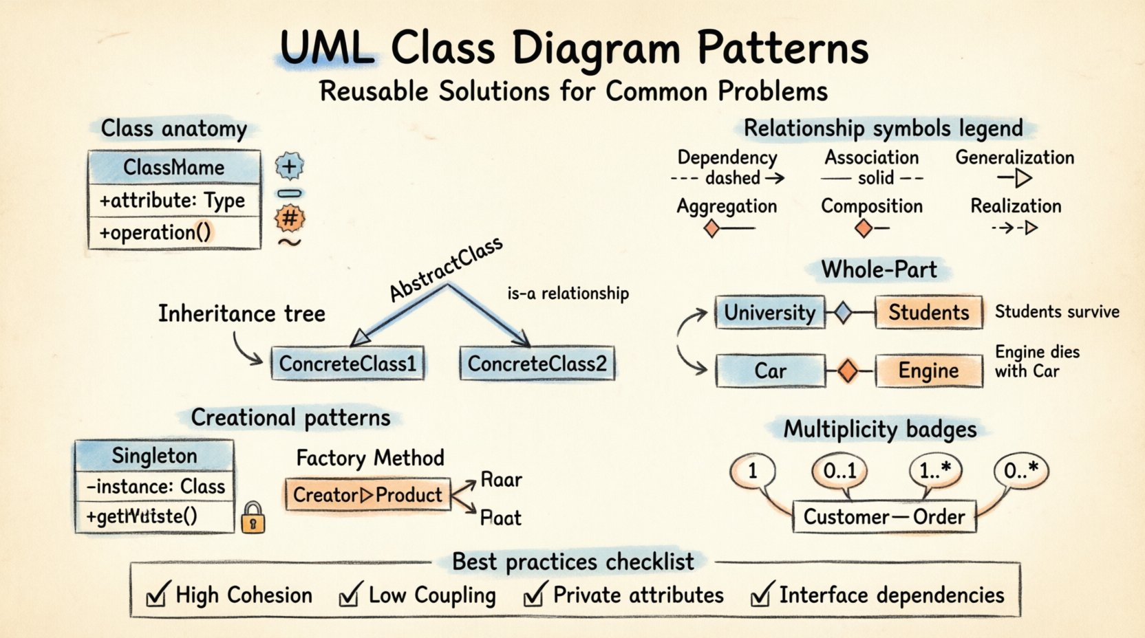
- Dependency (Dashed Line, Open Arrow): One class uses another temporarily (e.g., a method argument).
- Association (Solid Line): A structural link between objects.
- Aggregation (Hollow Diamond): A “has-a” relationship where parts can exist independently.
- Composition (Filled Diamond): A strong “has-a” relationship where parts depend on the whole.
- Generalization (Solid Line, Hollow Triangle): An “is-a” inheritance relationship.
- Realization (Dashed Line, Hollow Triangle): An implementation relationship where a class implements an interface.
Mastering these patterns requires practice. Start by modeling small domains, then expand to larger systems. Always ask: “Does this relationship accurately reflect the business rules?” If the answer is no, redraw it. The diagram is a communication tool, not just a technical artifact. It must be understood by developers, architects, and stakeholders alike.
By applying these reusable solutions, you ensure that your object-oriented designs are not just functional, but elegant and robust. The effort spent on creating precise Class Diagrams pays dividends during the coding and maintenance phases of the software development lifecycle.

