In the complex landscape of software development, the disconnect between business intent and technical implementation often leads to costly delays and rework. This gap exists where business stakeholders articulate needs in natural language, and engineers interpret them as code structures. The bridge across this divide is the Unified Modeling Language (UML), specifically the Class Diagram. This visual artifact serves as the contract between domain logic and system architecture.
Translating requirements into a Class Diagram is not merely a drawing exercise; it is a rigorous analytical process. It requires identifying entities, defining behaviors, and establishing relationships that accurately reflect the operational reality of the organization. A well-constructed diagram reduces ambiguity, guides coding efforts, and serves as documentation for future maintenance. This guide details the systematic approach to converting business requirements into a robust technical model.
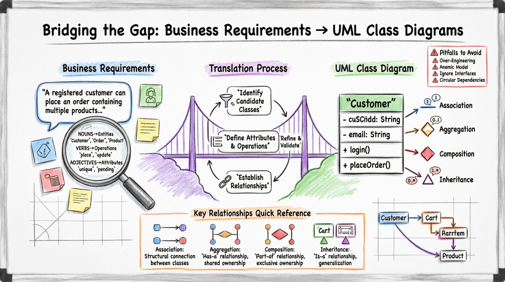
🔍 Understanding Business Requirements: The Foundation
Before drawing a single rectangle or line, one must thoroughly understand the source material. Business requirements are often written in prose, user stories, or functional specifications. They describe what the system should do, not how it should do it. The translator’s job is to extract the nouns and verbs that signify structure and behavior.
Effective analysis begins with identifying the core domain concepts. These are the objects that exist within the business context. For example, in a retail system, concepts include Customer, Order, Product, and Inventory. These nouns become the primary candidates for classes.
Key Steps in Requirement Analysis
- Read for Context: Understand the business domain before focusing on syntax.
- Identify Nouns: Highlight potential entities. These are your candidate classes.
- Identify Verbs: Highlight actions. These often translate to methods or operations.
- Identify Adjectives: Highlight attributes. These describe the state of the entities.
- Extract Constraints: Note rules regarding data types, limits, or mandatory fields.
Consider the following requirement statement:
“A registered customer can place an order containing multiple products. Each product must have a unique ID, and the order status must be updated to ‘Pending’ upon submission.”
From this single sentence, we extract:
- Entities: Customer, Order, Product.
- Attributes: Unique ID (for Product), Status (for Order).
- Actions: Place an order, Update status.
- Constraints: Multiple products per order, Unique ID requirement.
📐 Fundamentals of UML Class Diagrams
UML Class Diagrams are static structure diagrams. They depict the system’s blueprint, showing classes, their attributes, operations, and the relationships among objects. Unlike sequence diagrams which show behavior over time, class diagrams show the persistent structure.
Class Anatomy
Each class is typically represented as a compartmentalized rectangle divided into three sections:
- Name: The top section contains the class name. It should be a noun and capitalized (e.g.,
Customer). - Attributes: The middle section lists the properties or data members. Visibility modifiers (e.g.,
+,-,#) are often used. - Operations: The bottom section lists the methods or functions available to the class.
Relationships
Classes rarely exist in isolation. They interact through relationships that define how instances of classes relate to one another. The primary types of relationships include:
- Association: A structural relationship where objects are linked. It represents a “knows” relationship.
- Aggregation: A specific type of association representing a “whole-part” relationship where the part can exist independently of the whole.
- Composition: A stronger form of aggregation where the part cannot exist without the whole.
- Inheritance (Generalization): Represents an “is-a” relationship, where a subclass derives from a superclass.
🔄 The Translation Process: Step-by-Step
Converting text to a diagram requires a disciplined workflow. Rushing to the drawing board without a strategy often results in a cluttered or inaccurate model. The following process ensures clarity and accuracy.
Step 1: Identify Candidate Classes
Review the requirements text and highlight all significant nouns. Group them logically. Sometimes, nouns are too granular (e.g., “Address” inside “Customer”) or too broad (e.g., “System”). Filter the list to keep only those that represent significant business concepts.
Filtering Criteria:
- Significance: Does the object have state or behavior?
- Reusability: Is it used in multiple places?
- Complexity: Does it have internal logic or data?
Step 2: Define Attributes and Operations
For each selected class, define what data it holds and what it can do. Attributes come from adjectives or specific data fields in the requirements. Operations come from verbs describing actions performed on or by the entity.
Example:
- Class: Product
- Attributes: productId (String), price (Decimal), stockQuantity (Integer).
- Operations: calculateDiscount(), updateStock(), validatePrice().
Step 3: Establish Relationships
Connect the classes based on how they interact in the business process. This is often the most critical step. Misidentifying a relationship can lead to database schema errors later.
Ask the following questions to determine relationships:
- Does one object contain another? (Composition/Aggregation)
- Does one object reference another? (Association)
- Is one object a specialized type of another? (Inheritance)
📊 Mapping Requirements to Diagram Elements
The following table illustrates how specific types of business requirements map directly to UML Class Diagram elements. This reference aids in maintaining consistency during the modeling process.
| Requirement Type | Example Text | Diagram Element | Notes |
|---|---|---|---|
| Entity Definition | “The system tracks Users.” | Class: User |
Use nouns for class names. |
| Property Definition | “A User has an email address.” | Attribute: - email: String |
Specify data types where known. |
| Behavior Definition | “Users can log in.” | Operation: + login(): Boolean |
Verbs become methods. |
| Ownership | “An Order belongs to a Customer.” | Association (1:1 or 1:*) | Check multiplicity rules. |
| Part-Whole | “An Order consists of Line Items.” | Composition | Items die if the Order is deleted. |
| Specialization | “A Premium User is a standard User.” | Inheritance | Premium User extends User. |
🔗 Managing Relationships and Multiplicity
Relationships define the cardinality of connections between classes. Multiplicity specifies how many instances of one class relate to one instance of another. Correctly defining multiplicity is crucial for database normalization and query performance.
Common Multiplicities
- 1: Exactly one instance.
- 0..1: Zero or one instance (optional).
- 1..*: One or more instances.
- 0..*: Zero or more instances.
- * : Synonym for 0..*.
Scenario Analysis:
Consider a library system. A Book can be borrowed by a Member.
- Can a book exist without a member? Yes. Multiplicity on Member side: 0..*
- Can a member exist without a book? Yes. Multiplicity on Book side: 0..*
- Can a book be borrowed by multiple members simultaneously? No. Multiplicity is 1:1 at the time of borrowing, but over time it is 1:*.
It is vital to distinguish between Aggregation and Composition. Both imply a “whole-part” relationship, but the lifecycle differs.
- Aggregation: The part can exist independently. Example: A
DepartmenthasEmployees. If the department dissolves, the employees still exist. - Composition: The part depends on the whole. Example: A
HousehasRooms. If the house is demolished, the rooms cease to exist in that context.
🛠️ Iterative Refinement and Validation
Creating a Class Diagram is rarely a linear path. It is an iterative cycle of modeling, reviewing, and refining. The initial draft is a hypothesis that must be tested against the requirements.
Validation Checklist
Before finalizing the diagram, run through this checklist to ensure accuracy and completeness.
- Completeness: Are all business entities represented?
- Consistency: Do attribute names match across different classes?
- Clarity: Is the diagram readable? Avoid crossing lines where possible.
- Feasibility: Can the identified operations be implemented with the current technology stack?
- Normalization: Are there redundant attributes? Does the design support efficient data retrieval?
Handling Ambiguity
Requirements are often vague. A phrase like “process data” could mean validation, transformation, or storage. In the absence of clarity, make a documented assumption. Create a note in the diagram indicating that the assumption requires verification with stakeholders.
Example: If the requirement says “Store customer details,” does this include billing address, shipping address, or both? The diagram should reflect this distinction explicitly rather than lumping them into a generic “Address” class unless the business logic confirms they are identical.
⚠️ Common Pitfalls in Modeling
Even experienced modelers fall into traps. Being aware of common errors helps maintain the integrity of the design.
1. Over-Engineering
Creating abstract classes and deep inheritance hierarchies to solve hypothetical problems. Design for the requirements at hand, not for every potential future scenario. Keep the model simple (YAGNI – You Ain’t Gonna Need It).
2. Anemic Domain Model
Defining classes with attributes but no behavior. If a class has methods that modify its own state, it should be an object-oriented class, not just a data container. Ensure methods like calculateTotal() or validate() reside in the class where they logically belong.
3. Ignoring Interfaces
Classes often interact via contracts. If a class needs to accept different implementations of a service, define an interface or abstract class. This decouples the class from specific implementations, aiding flexibility.
4. Circular Dependencies
Ensure Class A does not depend on Class B, which depends on Class C, which depends back on Class A. This creates a cycle that complicates loading, testing, and maintenance. Break cycles by introducing interfaces or redefining responsibilities.
🚀 Practical Example: E-Commerce System
To solidify understanding, let us apply these principles to a simplified e-commerce scenario.
Requirements
- Customers can register and log in.
- Customers can browse categories of products.
- Customers can add items to a shopping cart.
- Orders are generated from the cart and include a total price.
Derived Classes
- Customer: Handles authentication and personal details.
- Product: Holds inventory and pricing data.
- Category: Groups products for browsing.
- Cart: Holds temporary items before checkout.
- Order: Finalized transaction record.
- CartItem: Specific instance of a product in a cart.
Relationships
- Customer owns Cart: Composition (If the customer leaves, the cart is cleared).
- Cart contains CartItem: Composition (CartItems die if Cart is removed).
- CartItem references Product: Association (Product exists independently).
- Order contains CartItem: Aggregation (Items are historical records).
📝 Final Thoughts on Structural Integrity
The quality of a software system often depends on the quality of its initial design. A UML Class Diagram is not a final destination but a tool for communication. It aligns the technical team with the business goals. When the diagram is clear, the code tends to follow naturally.
Focus on accuracy over speed. A diagram that is slightly slower to produce but accurately reflects the requirements saves weeks of debugging later. Treat the diagram as a living document that evolves as requirements change. Regularly revisit the model during sprint reviews to ensure it remains relevant.
By adhering to a structured translation process, you ensure that the business value is preserved in the code. The bridge between requirements and implementation becomes solid, allowing for sustainable growth and reliable delivery. This disciplined approach fosters confidence in the architecture and clarity for the entire development team.

