


Systems Modeling Language (SysML) serves as a specialized extension of the Unified Modeling Language (UML), tailored specifically for systems engineering. Within this framework, the Internal Block Diagram (IBD) stands as a critical artifact for defining the internal structure of a system. It moves beyond abstract definitions to show how components connect and interact.
This guide explores the mechanics, semantics, and practical application of Internal Block Diagrams. By mastering the internal composition of systems, engineers can ensure that interfaces are defined correctly and that data and physical flows are managed effectively throughout the development lifecycle. 🧩
What is an Internal Block Diagram? 📐
An Internal Block Diagram depicts the internal structure of a single block. It is used to show the parts that make up the block and the connections between those parts. While a Block Definition Diagram (BDD) defines the types of blocks and their relationships to other types, an IBD shows the instantiation of those blocks within a specific context.
Key characteristics include:
- Internal Focus: It details what is inside a specific block.
- Connections: It defines how data, signals, or physical matter flows between internal components.
- Composition: It illustrates the aggregation and composition relationships that build the system from its parts.
Core Elements of an IBD 🔧
To construct a meaningful Internal Block Diagram, one must understand the fundamental building blocks. Each element serves a specific purpose in modeling the system architecture.
1. Parts and Properties
A part represents an instance of a block type within the containing block. Parts are the physical or logical components that reside inside the system.
- Block Instances: When you place a block inside an IBD, it becomes a part of the parent block.
- Properties: These are the attributes of the block that can be accessed by other parts. Properties define the data or signals that flow through the system.
2. Ports
Ports define the interaction points of a block. They are the gateways through which parts communicate with the outside world or with other internal parts.
- Flow Ports: Represent the passage of data, signals, or physical matter. They are used for continuous flows.
- Part Ports: Represent the access to a specific part instance. These are often used for control or command signals. Interface Ports: Define a contract that the part must adhere to, ensuring compatibility with other components.
3. Connectors
Connectors link ports together, establishing the paths for information or material to travel. The type of connector determines the nature of the relationship.
- Flow Connectors: Used to connect flow ports. They indicate the transfer of data or physical quantity.
- Association Connectors: Used to connect part ports. They indicate a structural relationship or command path.
Ports and Connectors: A Detailed Look 🔗
The distinction between different types of ports and connectors is crucial for accurate modeling. Misinterpreting these elements can lead to design errors in the final system.
Flow Ports vs. Part Ports
Understanding when to use a flow port versus a part port is a common challenge.
- Flow Ports: Use these when the interaction involves the movement of something (data, energy, fluid). For example, a data stream moving from a sensor to a processor.
- Part Ports: Use these when the interaction is about control or access to a component. For example, a switch controlling a motor.
Connector Types
Just as there are different ports, there are different connector semantics.
- Association: Represents a structural link. It does not imply data flow.
- Flow: Represents an active transfer of information or material.
Interfaces and Usage 🌐
Interfaces define the services or signals that a block can provide or require. Using interfaces in an IBD promotes modularity and reduces coupling between components.
Provided vs. Required Interfaces
Interfaces can be classified based on their directionality.
- Provided Interfaces: The block offers a service. Other parts can use this interface to access functionality.
- Required Interfaces: The block needs a service. It depends on another part to fulfill this need.
Usage Relationships
When a block requires an interface provided by another block, a usage relationship is established. This relationship is often depicted with a specific stereotype in SysML.
Value Types and Reference Properties 📊
Systems often deal with complex data structures. SysML allows for the definition of value types and reference properties to handle this complexity within the IBD.
Value Types
Value types define simple data structures, such as integers, strings, or custom units like temperature or pressure. They are essential for defining the data that flows through flow ports.
Reference Properties
Reference properties allow a block to refer to an external object. This is useful when a part needs to interact with an object that exists outside the immediate system boundary.
Composition and Aggregation 🏛️
The internal structure of a system is built using composition relationships. These relationships define how parts are owned by a parent block.
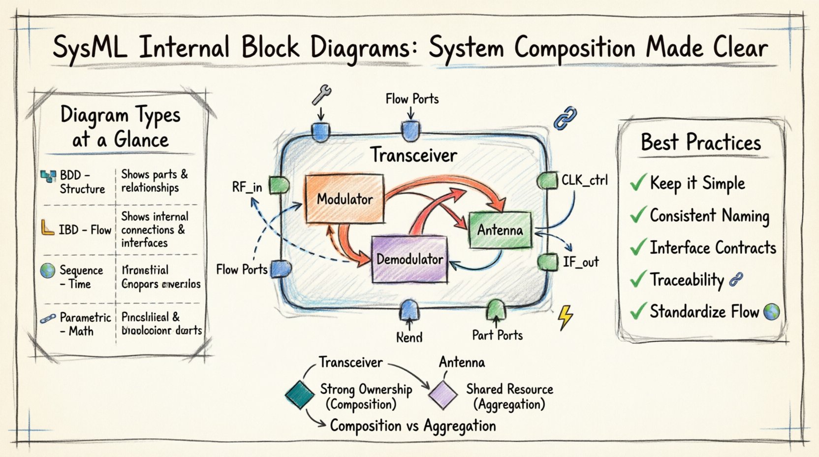
Composition
Composition implies a strong ownership. If the parent block is destroyed, the parts are also destroyed. This is the standard relationship for building a system from its components.
Aggregation
Aggregation implies a weaker ownership. The parts can exist independently of the parent block. This is used for shared resources or components that might be swapped out.
Best Practices for IBD Modeling 📝
Creating clear and maintainable diagrams requires adherence to specific modeling standards. Following these practices ensures that the diagrams remain useful throughout the project lifecycle.
- Keep it Simple: Avoid cluttering the diagram with too many parts. Use nesting to break down complexity.
- Consistent Naming: Use clear and descriptive names for all parts, ports, and connectors.
- Interface Contracts: Define interfaces explicitly to ensure components can be developed and tested independently.
- Traceability: Link parts and ports to requirements to ensure every component serves a defined purpose.
- Standardize Flow: Clearly distinguish between data flow and control flow to avoid ambiguity.
Comparing IBD with Other Diagrams 📋
Understanding where the IBD fits within the broader SysML suite is essential. It complements other diagrams rather than replacing them.
| Diagram Type | Primary Purpose | Key Focus |
|---|---|---|
| Block Definition Diagram (BDD) | Define block types and relationships | Structure and Hierarchy |
| Internal Block Diagram (IBD) | Define internal connections | Flow and Interaction |
| Sequence Diagram | Define temporal behavior | Time and Order |
| Parametric Diagram | Define constraints and equations | Mathematics and Limits |
Nesting and Abstraction Levels 📉
Complex systems often require multiple levels of abstraction. An IBD can be nested within another IBD to manage this complexity.
Deep Nesting
When a block contains another block, you can create an IBD for the outer block and another for the inner block. This allows you to hide details until they are needed.
Abstraction
Use abstraction to show high-level connections without detailing every internal wire. This keeps the diagram readable for stakeholders who do not need implementation details.
Common Pitfalls to Avoid ⚠️
Even experienced modelers can make mistakes. Being aware of common errors helps in maintaining diagram quality.
- Over-connecting: Connecting every part to every other part creates a “spaghetti” diagram that is hard to read.
- Mixing Flow and Control: Using flow connectors for control signals can confuse the data flow logic.
- Ignoring Interfaces: Failing to define interfaces can lead to integration issues when components are assembled.
- Missing Ports: Forgetting to define ports on parts can prevent connections from being made.
Integration with Requirements 📌
One of the strongest features of SysML is the ability to trace elements back to requirements. This ensures that the system composition meets the original goals.
- Requirement Traceability: Link each part or port to a specific requirement.
- Verification: Use the diagram to verify that all requirements are satisfied by the internal structure.
- Change Management: When requirements change, the traceability links help identify which parts need modification.
Example Scenario: A Communication System 📡
Consider a simplified communication system. The main block might be “Transceiver”.
- Parts: “Modulator”, “Demodulator”, “Antenna”.
- Ports: “Input Signal”, “Output Signal”, “Control”.
- Connectors: Connect “Input Signal” port to “Modulator”. Connect “Modulator” to “Demodulator”.
- Interface: Define a “Data Interface” for the signal flow.
This structure allows engineers to simulate the signal path before building the hardware.
Conclusion and Next Steps 🚀
The Internal Block Diagram is a powerful tool for systems engineering. It provides the necessary detail to understand how a system works internally while maintaining a high-level view of the architecture. By focusing on parts, ports, and connectors, engineers can create robust models that support development and testing.
Continuing to refine your skills in SysML modeling will lead to better system designs. Focus on clarity, consistency, and traceability to ensure your models remain valuable assets throughout the project.

