Welcome to this comprehensive guide on Systems Modeling Language (SysML). This resource is designed to clarify the fundamental concepts of model-based systems engineering without relying on specific vendor tools. Whether you are an engineer transitioning from traditional documentation or a student entering the field, understanding the structure of SysML is essential for modern system development. We will address common queries with detailed, technical explanations to build a solid foundation.
🧩 1. What Exactly Is SysML?
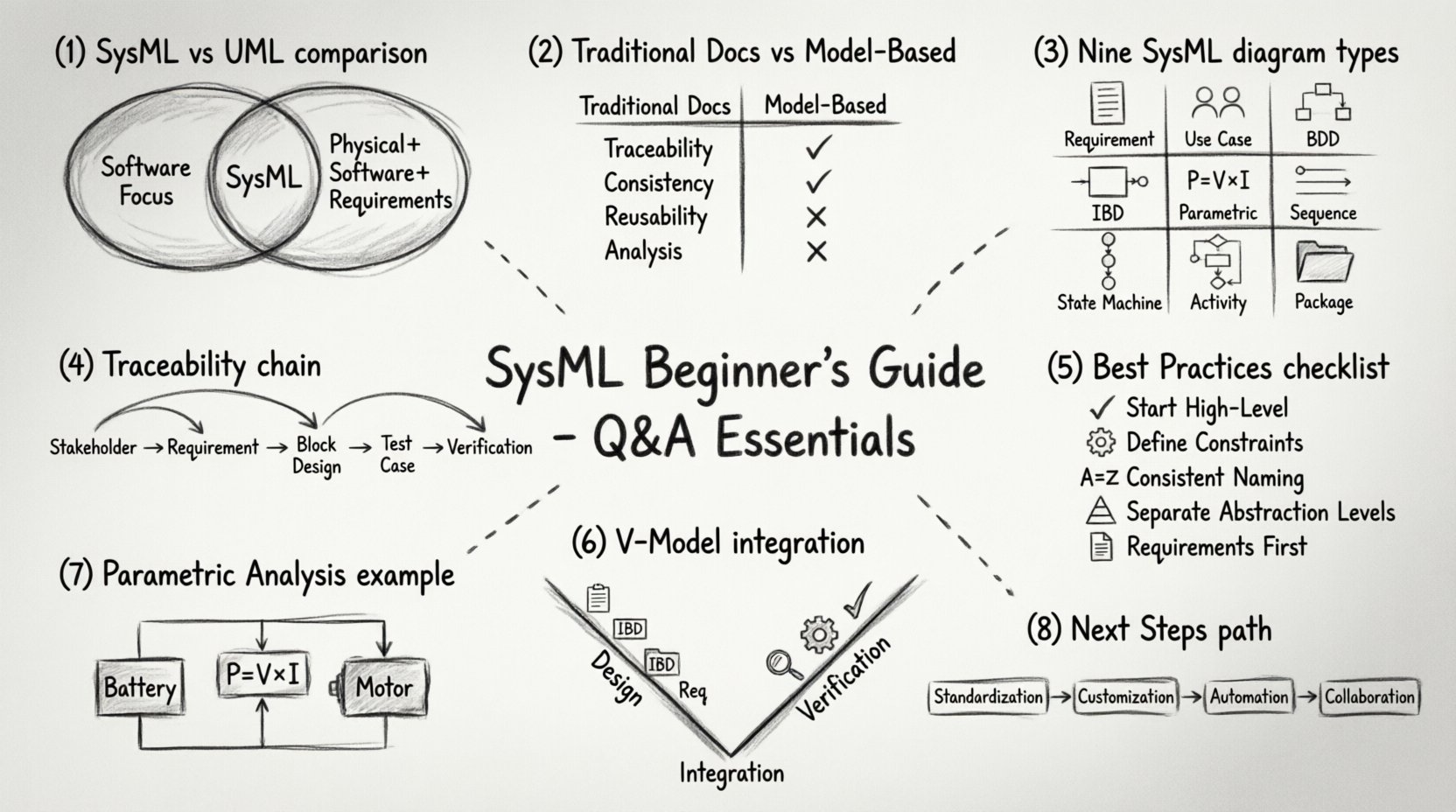
Q: How does SysML differ from UML, and why is it necessary for systems engineering?
SysML is a general-purpose modeling language for systems engineering applications. It is a profile of the Unified Modeling Language (UML), meaning it reuses UML concepts but extends them to meet the specific needs of systems engineering. While UML focuses heavily on software structure and behavior, SysML broadens the scope to include physical components, performance requirements, and resource flows.
Key distinctions include:
- Requirements: SysML has a dedicated diagram type for managing requirements, which is often less emphasized in standard UML.
- Parametrics: It includes a diagram type for mathematical constraints and performance analysis, crucial for physical systems.
- Blocks: The block concept in SysML is more versatile, representing anything from software to hardware to services.
- Allocations: It explicitly supports mapping requirements and functions to physical components.
For a systems engineer, SysML provides a standardized way to represent system architecture, behavior, and requirements in a single, coherent model. This reduces ambiguity and improves communication across multidisciplinary teams.
📊 2. Why Use Modeling Instead of Word Documents?
Q: Is it worth the effort to learn a modeling language when spreadsheets and documents are familiar?
Traditional documentation methods often suffer from version control issues, disconnected data, and manual updates. When a change occurs in a requirement, updating a Word document and ensuring linked diagrams are updated manually is error-prone. A modeling environment maintains the integrity of the model.
Here is a comparison of traditional methods versus model-based approaches:
| Feature | Traditional Documentation (Word/Excel) | Model-Based Approach (SysML) |
|---|---|---|
| Traceability | Manual hyperlinking or text references | Automated bidirectional links between elements |
| Consistency | High risk of human error during updates | Model checks ensure consistency across views |
| Reusability | Copying text is difficult to manage | Blocks and patterns can be reused across projects |
| Analysis | Limited to manual calculations | Integrated parametric analysis capabilities |
By centralizing system information, engineers can focus on design and analysis rather than administrative data maintenance. This leads to higher quality systems and reduced lifecycle costs.
📐 3. Understanding the Core Diagrams
Q: What are the nine diagram types in SysML, and when should I use each?
SysML defines nine specific diagram types to capture different aspects of a system. Mastering these requires understanding the specific information each diagram conveys.
3.1 Requirement Diagrams
This diagram manages the lifecycle of requirements. It allows you to define requirements, assign identifiers, and track their status. Crucially, it enables relationships like refinement, satisfaction, and verification. You can link a requirement to a test case to ensure it is validated later in the process.
3.2 Use Case Diagrams
These diagrams illustrate the functional requirements from the perspective of an actor. They define the interactions between the system and its users or external systems. Use cases describe what the system does, not how it does it. This is ideal for capturing high-level scope and stakeholder interactions.
3.3 Block Definition Diagrams (BDD)
The BDD is the structural backbone of your model. It defines the blocks (components) and their relationships. Relationships include:
- Association: A static link between blocks.
- Generalization: Inheritance or categorization (e.g., a specific engine is a type of engine).
- Composition: A strong ownership relationship (e.g., a car contains an engine).
- Dependency: One block relies on another to function.
3.4 Internal Block Diagrams (IBD)
While the BDD shows the high-level structure, the IBD shows the internal structure of a block. It displays ports, connectors, and value properties. This is where you define how data and material flow between internal parts. It is essential for defining interfaces and physical connectivity.
3.5 Parametric Diagrams
This is a unique feature for systems engineering. Parametric diagrams allow you to express constraints and equations. For example, you can define a relationship where Power = Voltage × Current. This enables early performance analysis and trade-off studies without writing code.
3.6 Sequence Diagrams
These diagrams show the flow of messages between objects over time. They are similar to UML sequence diagrams but applied to system elements. They are vital for understanding dynamic behavior and interaction sequences between subsystems.
3.7 State Machine Diagrams
State machines describe the lifecycle of a block. They define states, transitions, events, and actions. This is useful for systems with complex operational modes, such as a drone switching from “Hover” to “Return to Home”.
3.8 Activity Diagrams
Activity diagrams model the flow of control or data. They are similar to flowcharts and are used to describe complex workflows, algorithms, or processes. They support concurrency, which is important for systems that perform multiple operations simultaneously.
3.9 Package Diagrams
These diagrams organize the model. Just as folders organize files on a computer, packages organize model elements. They help manage complexity by grouping related diagrams and elements into namespaces.
🔗 4. Requirements and Traceability
Q: How do I ensure my requirements are actually met by the design?
Traceability is the ability to follow a requirement from its origin through to its verification. In SysML, this is managed through the Requirement Diagram and relationships.
To establish robust traceability, follow these steps:
- Define Origin: Specify where the requirement comes from (e.g., a stakeholder, a regulation, or a higher-level requirement).
- Link to Design: Use the “Satisfy” relationship to link a requirement to a block or function that fulfills it.
- Link to Test: Use the “Verify” relationship to link a requirement to a test case or validation activity.
- Check Coverage: Regularly review the model to ensure every requirement has a corresponding design element and test.
This chain of evidence is critical for certification processes in industries like aerospace, medical devices, and automotive. It proves that the system was built to meet the specified needs.
⚙️ 5. Modeling Best Practices
Q: What are common mistakes beginners make when starting with SysML?
Even experienced engineers can fall into traps when modeling complex systems. Avoid these common pitfalls to maintain model quality.
- Over-Modeling: Do not model every single detail immediately. Start with the architecture and high-level flows. Add detail only as necessary for clarity or analysis.
- Ignoring Constraints: Do not forget to define constraints on blocks. Properties like mass, power, and dimensions should be defined early to enable parametric analysis.
- Poor Naming: Use consistent naming conventions. A block named “Motor” is better than “Block1”. Consistency aids navigation and understanding.
- Mixing Levels of Abstraction: Keep your diagrams focused. Do not mix high-level system architecture with low-level component implementation in the same diagram unless necessary for interface definition.
- Skipping Requirements: Never start with diagrams without requirements. The requirements drive the design, not the other way around.
🔄 6. Integration into the Engineering Lifecycle
Q: How does SysML fit into the V-Model or Agile processes?
SysML is process-agnostic. It can be used within the traditional V-Model of systems engineering or adapted for Agile methodologies.
In the V-Model:
- Left Side (Design): SysML is used to define requirements, architecture, and behavior.
- Right Side (Verification): The model is used to derive test cases and verify that the physical system meets the modeled requirements.
- Bottom (Integration): The model serves as the system of record during integration.
In Agile:
- Iterative Refinement: Models are updated in sprints. High-level architecture is established first, with details added incrementally.
- Living Documentation: The model is the primary source of truth, updated continuously rather than being a static document produced at the end of a phase.
📈 7. Analyzing Performance with Parametrics
Q: Can I actually calculate values using the model?
Yes. Parametric diagrams allow you to define equations using constraint blocks. You can link these to blocks in your structure.
Example Scenario:
- You have a Battery Block with properties for Voltage and Capacity.
- You have a Motor Block with properties for Power and Efficiency.
- You define a Constraint Block for Power:
Power = Voltage * Current. - You link the Voltage from the Battery and the Current from the Motor to the constraint.
This setup allows you to simulate scenarios. If you change the Voltage, the model can calculate the resulting Power consumption. This is invaluable for sizing components and ensuring they fit within physical limits.
🚀 8. Moving Forward
Q: What is the next step after learning the basics?
Once you are comfortable with the core diagrams and requirements, focus on advanced topics.
- Standardization: Learn the latest versions of the SysML standard to ensure compatibility.
- Customization: Explore how to create custom profiles for your specific industry needs.
- Automation: Look into scripting or integration with other engineering tools for data exchange.
- Collaboration: Practice working with distributed teams using shared model repositories.
Systems engineering is a continuous journey. The complexity of modern systems demands tools that can handle that complexity. SysML provides the structure and language to manage this complexity effectively. By mastering these concepts, you contribute to more reliable, efficient, and safe systems.
📝 Final Thoughts
Adopting SysML requires a shift in mindset from documentation to modeling. It is not merely about drawing boxes and lines; it is about creating a precise, analyzable representation of the system. The effort invested in learning the language pays off through improved communication, reduced errors, and better system performance.
Remember to start small, focus on requirements first, and gradually expand the scope of your models. With practice and adherence to best practices, SysML becomes a powerful asset in your engineering toolkit. Keep refining your approach and stay curious about the capabilities of model-based engineering.
This guide covers the foundational questions and answers necessary to begin your journey. For deeper technical inquiries, consult the official language specifications or engage with the systems engineering community for peer review and feedback.

