Systems engineering demands precision, clarity, and a unified approach to complex problem-solving. The Systems Modeling Language (SysML) provides a standardized framework for specifying, analyzing, designing, and verifying systems. This guide explores the core components of SysML without relying on specific software tools, focusing instead on the theoretical and practical application of the language itself.
Complex systems today involve multiple domains, including software, hardware, and human interaction. A single modeling language bridges these gaps. By standardizing the representation of system architecture, behavior, and requirements, engineers can ensure alignment across teams. This walkthrough covers the essential diagram types and modeling techniques required to build robust system definitions.
Understanding the SysML Framework 🛠️
SysML is a general-purpose modeling language suitable for the specification, analysis, design, and verification of a wide range of systems and systems of systems. It is based on the Unified Modeling Language (UML) but extends it with specific capabilities for systems engineering.
Key characteristics of the language include:
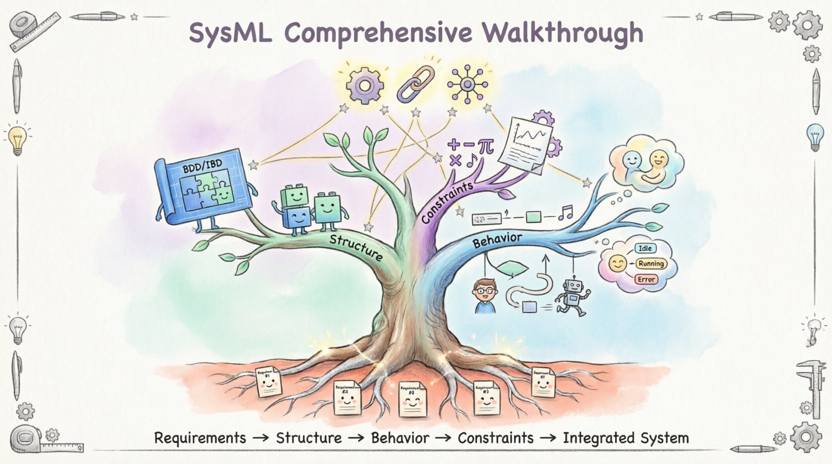
- Multi-paradigm support: It handles requirements, structure, behavior, and constraints within a single model.
- Reusability: Models can be reused across different projects and system lifecycles.
- Traceability: Relationships between requirements, design elements, and verification tests are explicitly defined.
- Interoperability: Standardized syntax allows data exchange between different engineering domains.
Unlike traditional documentation methods, SysML uses graphical representations. These diagrams provide a visual syntax that is often easier to interpret than text-heavy specifications. This visual nature reduces ambiguity and helps stakeholders identify conflicts early in the development process.
The Requirements Diagram 📋
Requirements engineering is the foundation of any systems project. The Requirements Diagram in SysML is dedicated to capturing and organizing stakeholder needs. It ensures that every design decision can be traced back to a specific requirement.
Core Elements of Requirements
Within the requirements framework, specific elements define the nature of the need:
- Requirement Blocks: These represent individual requirements. Each block contains properties such as ID, name, description, and verification method.
- Constraint Blocks: These are used to define specific constraints or rules that apply to requirements.
- Relationships: Links such as satisfy, refine, verify, and derive connect requirements to other model elements.
Traceability Matrix
Traceability is the ability to track the lifecycle of a requirement from inception to verification. The Requirements Diagram facilitates this through explicit links:
- Satisfied: Indicates that a design element fulfills a specific requirement.
- Refined: Breaks down a high-level requirement into more detailed sub-requirements.
- Verified: Links a requirement to a test or analysis that confirms compliance.
- Derives: Shows that a new requirement is derived from an existing one.
By maintaining these links, engineers can perform impact analysis. If a requirement changes, the model instantly highlights all affected design elements. This reduces the risk of regression and ensures system integrity.
Defining System Structure 🔧
Structure diagrams describe the static architecture of a system. They define the parts that make up the system and how those parts are connected. This is the physical or logical skeleton of the engineering effort.
Block Definition Diagrams (BDD)
The Block Definition Diagram is the primary structural diagram. It defines the types of blocks available in the system.
- Blocks: These are the fundamental units of structure. A block can represent a physical component, a software module, or a logical function.
- Properties: Attributes that belong to a block, such as mass, voltage, or data type.
- Operations: Functions that the block can perform.
- Relationships: Generalization, aggregation, and association define how blocks relate to one another.
For example, a vehicle system might contain blocks for an engine, a battery, and a control unit. The BDD defines the interface and internal composition of these blocks without detailing the specific connections in a single instance.
Internal Block Diagrams (IBD)
While BDDs define types, Internal Block Diagrams define instances and connections. They show how specific blocks are connected via ports and connectors.
- Parts: Specific instances of blocks placed within a composite block.
- Ports: Points of interaction where parts connect to the outside world or other internal parts.
- Connectors: Links that define the flow of data, power, or material between ports.
- Flow Properties: Define the type of information moving through a connector.
This level of detail is crucial for understanding data flow and physical interfaces. It allows engineers to validate that the internal architecture supports the external interfaces defined in the requirements.
Specifying System Behavior 🔄
Structure defines what the system is, while behavior defines what the system does. SysML provides several diagram types to capture dynamic aspects of the system.
Use Case Diagrams
Use Case Diagrams capture the functional requirements from the perspective of an actor. They are essential for understanding who or what interacts with the system.
- Actors: Users, external systems, or hardware that interact with the system.
- Use Cases: Specific functions or goals the actor wants to achieve.
- Associations: Lines connecting actors to use cases.
- Includes/Extends: Relationships that define optional or mandatory behaviors.
Activity Diagrams
Activity Diagrams model the flow of control and data within a system. They are similar to flowcharts but offer more robust capabilities for concurrent processing.
- Actions: Steps in the process that transform inputs to outputs.
- Control Flow: The sequence in which actions occur.
- Data Flow: The movement of objects between actions.
- Forks and Joins: Mechanisms for modeling parallel execution paths.
This diagram type is particularly useful for modeling algorithms, business processes, or operational procedures. It helps identify bottlenecks and ensures all logical paths are covered.
Sequence Diagrams
Sequence Diagrams focus on the interaction between objects over time. They depict messages exchanged between lifelines.
- Lifelines: Representations of participants in the interaction.
- Messages: Arrows indicating communication between participants.
- Activation Bars: Indicate when an object is actively processing a message.
- Combined Fragments: Define loops, alternatives, or parallel interactions.
These diagrams are vital for defining interface protocols and timing constraints. They ensure that the order of operations is correct and that dependencies between components are managed properly.
State Machine Diagrams
State Machine Diagrams describe the lifecycle of an object or system in response to events.
- States: Conditions during which the system exhibits behavior.
- Transitions: Movements from one state to another triggered by events.
- Events: Occurrences that trigger a transition.
- Actions: Activities performed during entry, exit, or transition of a state.
This is essential for systems with complex logic, such as flight control systems or medical devices. It ensures that the system handles all possible states and error conditions gracefully.
Parametric Diagrams and Constraints ⚙️
Parametric Diagrams link the structural and behavioral models to mathematical constraints. They allow engineers to analyze the system using equations and physical laws.
- Constraint Blocks: Define mathematical relationships between variables.
- Constraint Properties: Specific instances of constraint blocks.
- Binding Connectors: Link constraint properties to block properties.
This capability enables system optimization and performance analysis. For instance, engineers can model the thermal constraints of a battery pack and link them to the electrical load requirements. This ensures that the design meets physical limits before manufacturing begins.
Integration and Traceability 🔗
One of the primary strengths of SysML is the integration of all these views into a single coherent model. Traceability links connect requirements to structure and behavior.
Effective integration relies on:
- Consistent Naming: Using standard naming conventions ensures elements are easily identifiable across diagrams.
- Modularization: Breaking the model into packages prevents complexity from becoming unmanageable.
- Version Control: Managing changes to the model ensures that all stakeholders work from the same baseline.
- Validation: Regular checks ensure that the model remains consistent and error-free.
When a change occurs in a requirement, the traceability links allow the engineer to see exactly which blocks and behaviors are impacted. This reduces the cost of changes and minimizes the risk of introducing errors.
Diagram Type Overview
| Diagram Type | Primary Purpose | Key Elements |
|---|---|---|
| Requirements Diagram | Capture and manage stakeholder needs | Requirements, Relationships |
| Block Definition Diagram | Define system types and hierarchy | Blocks, Properties, Operations |
| Internal Block Diagram | Define connections and interfaces | Parts, Ports, Connectors |
| Activity Diagram | Model process flow and logic | Actions, Control Flow, Data Flow |
| Sequence Diagram | Model interactions over time | Lifelines, Messages, Activation |
| State Machine Diagram | Model state transitions | States, Transitions, Events |
| Parametric Diagram | Model mathematical constraints | Constraints, Binding Connectors |
Implementation Best Practices ✅
Successful modeling requires adherence to established practices. These guidelines help maintain model quality and usability.
- Start with Requirements: Always begin with a clear set of requirements. This ensures the model serves a purpose.
- Keep Models Modular: Use packages to separate concerns. Do not place all elements in a single diagram.
- Standardize Notation: Follow standard SysML notation rules to ensure readability by all team members.
- Review Regularly: Conduct model reviews with stakeholders to validate accuracy and completeness.
- Document Assumptions: Clearly document any assumptions made during the modeling process.
These practices ensure that the model remains a living artifact that supports the project throughout its lifecycle.
Common Modeling Challenges ⚠️
Even with a robust language, challenges arise. Understanding these helps in mitigation.
- Complexity: Large systems can lead to overly complex models. Use abstraction to manage this.
- Inconsistency: Changes in one part of the model may not be reflected elsewhere. Enforce strict traceability.
- Tooling Limitations: While this guide avoids specific tools, different platforms handle model management differently. Ensure the workflow supports the modeling approach.
- Stakeholder Engagement: Ensuring all stakeholders understand the model requires training and clear communication.
Future Considerations in Systems Engineering 🚀
The landscape of systems engineering continues to evolve. New standards and practices emerge regularly. SysML remains a stable core, but its integration with other standards is increasing.
- Model-Based Systems Engineering (MBSE): The shift from document-based to model-based approaches is accelerating.
- Simulation: Models are increasingly used for simulation before physical prototyping.
- Integration with AI: Automated analysis and optimization are becoming more common.
Staying informed about these trends ensures that the modeling practices remain relevant and effective. The goal is always to deliver systems that meet their objectives efficiently and reliably.
Conclusion on Modeling Standards
Adopting SysML provides a structured approach to handling system complexity. By clearly defining requirements, structure, and behavior, teams can reduce risk and improve communication. The language offers the flexibility to model diverse systems while maintaining a consistent standard. Following best practices and understanding the core diagram types ensures that the model serves its intended purpose effectively.
Continuous improvement in modeling techniques leads to better system outcomes. Engineers who master these concepts contribute to more robust and reliable systems. The journey involves learning the language, applying it consistently, and refining the approach based on project feedback.

