Systems engineering is a discipline that focuses on designing, integrating, and managing complex systems over their life cycles. As the industry shifts toward Model-Based Systems Engineering (MBSE), the Systems Modeling Language (SysML) has become the standard for visualizing system architectures. However, simply knowing the syntax is not enough. A structured approach ensures consistency, clarity, and traceability throughout the development process.
This guide provides a rigorous checklist designed for engineers new to the field. It covers the essential phases of creating a robust system model without relying on specific commercial tools. The focus remains on the methodology, the language specifications, and the engineering principles that drive successful MBSE implementation. 📝
Why a SysML Checklist Matters 📋
Complex systems involve multiple stakeholders, varying levels of abstraction, and strict requirements. Without a standardized checklist, models can become disjointed, making it difficult to trace requirements to design elements. A systematic approach helps in:
- Ensuring Consistency: Every diagram follows the same structural rules.
- Improving Communication: Visual models serve as a common language for hardware, software, and operations teams.
- Reducing Errors: Early detection of logical gaps before physical implementation begins.
- Facilitating Traceability: Linking requirements directly to system components.
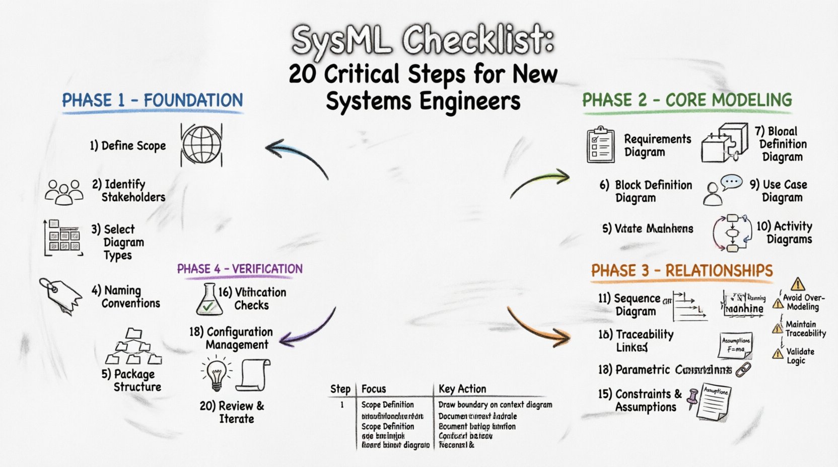
The following 20 steps are categorized into four logical phases to guide you from initial setup to final verification.
Phase 1: Foundation and Setup 🏗️
Before drawing a single box or line, you must establish the ground rules. This phase sets the stage for a maintainable model.
1. Define the System Scope and Boundaries 🌍
Clearly articulate what is inside the system and what is outside. This prevents scope creep and ensures that external interfaces are correctly identified. Document the context of the system relative to its environment. This definition anchors all subsequent modeling activities.
2. Identify Stakeholders and Needs 👥
Every system serves a purpose for someone. List all stakeholders, including end-users, operators, maintainers, and regulators. Capture their primary concerns and operational goals. These needs will eventually translate into formal requirements within the model.
3. Select Appropriate Diagram Types 📊
SysML offers several diagram types, but not all are needed for every project. Choose the diagrams that best communicate the specific information required for each phase. Common choices include Use Case, Block Definition, Internal Block, and Parametric diagrams.
4. Establish Naming Conventions 🏷️
Consistency is key for readability. Define rules for naming packages, blocks, requirements, and relationships. Use prefixes or suffixes to indicate status or type. For example, using RQ for requirements or BLK for blocks can help automated tools and humans parse the model structure easily.
5. Set Up Package Structure 📁
Organize the model into a logical hierarchy. Use packages to group related diagrams and elements. A typical structure might separate Requirements, Architecture, Behavior, and Analysis. This organization aids in navigation and version control.
Phase 2: Core Modeling Elements 🧱
With the foundation laid, you begin to define the structure and behavior of the system. This is the core of SysML modeling.
6. Create the Requirements Diagram 📝
Start by capturing all system requirements. Use the Requirement element to define hierarchical needs. Group them logically (e.g., Functional, Performance, Safety). Ensure every requirement has a unique identifier and a clear description.
7. Define the Block Definition Diagram (BDD) 🧩
The BDD represents the static structure of the system. Define the top-level blocks that make up the system. Decompose these blocks into sub-blocks. This hierarchy mirrors the physical or logical decomposition of the system.
8. Define the Internal Block Diagram (IBD) 🔌
While BDD shows blocks, IBD shows the connections between them. Define the parts, ports, and connectors. Ports act as interfaces where interactions occur. Connectors represent the flow of data, material, or energy between parts.
9. Develop the Use Case Diagram 🎯
Use Case diagrams describe how actors interact with the system. Identify the actors (users or external systems) and the goals they wish to achieve. These goals become the functional requirements or use cases within the model.
10. Model Basic Behavior with Activity Diagrams 🔄
Activity diagrams illustrate the flow of control and data within the system. Define actions, decision nodes, and object flows. This helps in understanding the operational sequence of the system without getting bogged down in timing details yet.
Phase 3: Relationships and Constraints 🔗
Systems are defined not just by what they are, but by how they relate to each other and the constraints they must satisfy.
11. Define the Sequence Diagram ⏱️
Sequence diagrams show interactions between objects over time. They are crucial for understanding the order of operations and message passing between system components. Use them to validate the logic defined in activity diagrams.
12. Model State Behavior with State Machine Diagrams ⏸️
Many system components have distinct states (e.g., Off, Standby, Running). Use State Machine diagrams to define these states and the transitions that trigger changes. This is vital for embedded systems and control logic.
13. Apply Constraints with Parametric Diagrams ⚖️
Parametric diagrams link physical properties to mathematical constraints. Define equations that govern the system behavior (e.g., Thrust = Mass × Acceleration). This allows for quantitative analysis and performance validation within the model.
14. Establish Traceability Links 🔄
Traceability is the backbone of MBSE. Link requirements to the blocks that satisfy them. Link requirements to the test cases that verify them. Use the “Refine” and “Satisfy” relationships to create a clear path from need to implementation.
15. Define Constraints and Assumptions 📌
Not everything is known. Document assumptions explicitly. If a requirement relies on a future technology or external condition, note it. This prevents false confidence in the model’s completeness.
Phase 4: Verification, Validation, and Maintenance 🚀
Once the model is built, it must be checked against reality and maintained over time.
16. Perform Verification Checks ✅
Verification answers the question, “Did we build the system right?” Check that the model elements comply with the syntax rules of the language. Ensure that all required diagrams exist and are populated with the correct data.
17. Perform Validation Checks 🧪
Validation answers the question, “Did we build the right system?” Compare the model against stakeholder needs. Does the system architecture actually solve the problem defined in the initial scope? This often involves simulation or analysis.
18. Manage Configuration and Versioning 📂
Models evolve. Establish a process for managing changes. Keep track of which version of the model corresponds to which project milestone. This is essential for audits and for reverting to previous states if a change introduces errors.
19. Document Assumptions and Rationales 💡
Future engineers need to understand why decisions were made. Add annotations or documentation blocks explaining the rationale behind major architectural choices. This preserves institutional knowledge.
20. Review and Iterate Continuously 🔄
Systems engineering is iterative. Schedule regular reviews with stakeholders. Update the model as requirements change. A static model becomes obsolete quickly. Continuous refinement ensures the model remains a living artifact of the system.
Summary of Critical Steps 📋
To assist in quick reference, here is a summary of the 20 steps outlined above.
| Step | Focus Area | Key Action |
|---|---|---|
| 1 | Scope | Define boundaries |
| 2 | Stakeholders | Identify needs |
| 3 | Diagram Selection | Choose types |
| 4 | Standards | Set naming rules |
| 5 | Organization | Structure packages |
| 6 | Requirements | Create Requirement Diagram |
| 7 | Structure | Define BDD |
| 8 | Interconnection | Define IBD |
| 9 | Interaction | Develop Use Case |
| 10 | Flow | Model Activity |
| 11 | Sequence | Define Sequence |
| 12 | State | Model State Machine |
| 13 | Math | Apply Parametric |
| 14 | Links | Establish Traceability |
| 15 | Logic | Define Constraints |
| 16 | Check | Perform Verification |
| 17 | Fit | Perform Validation |
| 18 | Control | Manage Configuration |
| 19 | Knowledge | Document Rationale |
| 20 | Growth | Review and Iterate |
Common Pitfalls to Avoid ⚠️
Even with a checklist, new engineers often encounter specific challenges. Being aware of these common issues can save significant time.
- Over-Modeling: Do not attempt to model every detail of the system immediately. Start with high-level architecture and refine as needed. Too much detail too early can obscure the big picture.
- Ignoring Traceability: A model without traceability is just a drawing. Ensure every requirement links to a design element.
- Inconsistent Notation: Using different symbols for the same concept confuses readers. Adhere strictly to the SysML standard notation.
- Lack of Context: Do not model the system in isolation. External interfaces are often the source of integration failures.
- Skipping Validation: A model can be syntactically correct but logically flawed. Always validate against actual system goals.
Integrating with the Engineering Lifecycle 🔗
SysML does not exist in a vacuum. It integrates with the broader systems engineering lifecycle. The checklist steps should align with project milestones. For instance, requirements definition should happen early, while parametric analysis might occur later during the design phase. This alignment ensures that the model provides value at every stage of development.
Collaboration is also critical. SysML models are often viewed by non-engineers. Keep diagrams clean and avoid unnecessary complexity. Use comments and annotations to explain technical details where the diagram alone might be insufficient.
Final Thoughts on Model Quality 🎯
The quality of a systems engineering model depends on the rigor applied during its creation. Following a structured checklist helps maintain this rigor. It ensures that the model is not just a visual aid, but a reliable source of truth for the project. By adhering to these 20 steps, engineers can build systems that are robust, verifiable, and aligned with stakeholder needs.
Remember that the model is a tool for thinking, not just a record of decisions. It should evolve as the project evolves. Continuous review and adherence to the fundamental principles of SysML will lead to better system outcomes. Focus on clarity, consistency, and traceability in every step of the process. 🛠️

