Systems engineering demands precision. It requires a language that bridges the gap between abstract requirements and concrete implementation. The Systems Modeling Language (SysML) provides this bridge, and within its suite of diagrams, the Block Definition Diagram (BDD) stands as the cornerstone of structural modeling. Whether you are designing a complex aerospace system, a medical device, or a software architecture, understanding how to construct a BDD is fundamental.
This guide explores the mechanics of drawing Block Definition Diagrams. It focuses on the semantics of the language, the logic behind relationships, and the discipline required to maintain clarity. No specific software tools are mentioned; the principles apply universally across modeling environments. The goal is to build a mental model of system structure that holds up under scrutiny.
Understanding the Block Definition Diagram 🧠
A Block Definition Diagram defines the static structure of a system. It describes the parts that make up the whole, how they relate to one another, and the responsibilities assigned to each component. Unlike the Internal Block Diagram (IBD), which focuses on the flow of data and signals between parts, the BDD focuses on the definitions themselves.
What Does a BDD Represent?
Think of a BDD as the blueprint of a house’s foundation and load-bearing walls. It tells you what materials are used and how the walls connect, but it does not show the wiring or plumbing routing. In SysML terms:
- Blocks are the primary unit of abstraction. They represent a system, a subsystem, or a component.
- Relationships define how blocks interact structurally.
- Properties describe the attributes or data held by a block.
- Operations describe the behaviors or actions a block can perform.
When drawn correctly, a BDD allows stakeholders to understand the system’s composition without needing to trace complex behavioral flows. It answers the question: “What is the system made of?”
Core Building Blocks of SysML 🧱
To draw a BDD with confidence, you must understand the atoms of the language. Each element has a specific semantic meaning that influences how the model is interpreted.
1. The Block
A Block is a composite element. It encapsulates structure and behavior. In a diagram, a block is represented by a rectangle with a specific compartment for properties and operations. Blocks can be:
- System Blocks: The top-level entity being designed.
- Subsystem Blocks: Major components within the system.
- Component Blocks: Physical or logical parts that can be replaced.
- Package Blocks: Used for organizing other blocks (similar to namespaces).
2. Properties vs. Parts vs. References
This is a common area of confusion. All three define relationships, but the semantics differ significantly.
| Element | Semantics | Example |
|---|---|---|
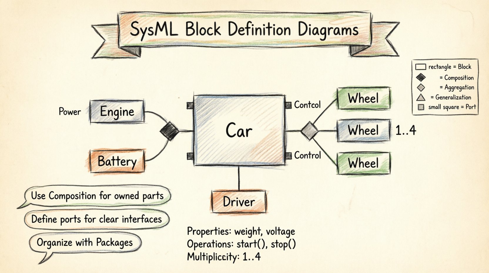
| Property | A scalar value or simple attribute held by the block. | Weight, Voltage, Color |
| Part | An internal component that belongs to the block. The part cannot exist without the owner. | Engine in a Car, Battery in a Phone |
| Reference | A connection to an external block. The referenced block may exist independently. | Driver in a Car, Charger in a Phone |
Using the correct terminology ensures that the model accurately reflects the lifecycle and ownership of system components. If a part is destroyed, the whole is affected. If a reference is removed, the block may still function, just differently.
Relationships and Connectivity 🔗
The power of SysML lies in how blocks connect. A diagram with blocks but no connections is just a list of parts. The relationships define the architecture.
1. Association
An association represents a structural connection between two blocks. It indicates that instances of one block can be linked to instances of another. It is the most general form of relationship.
- Direction: Associations can be unidirectional or bidirectional.
- Multiplicity: Defines how many instances are involved (e.g., 1..*, 0..1).
- Usage: Use this for general links where ownership is not implied.
2. Aggregation
Aggregation represents a “whole-part” relationship where the part can exist independently of the whole. It is a weak form of ownership.
- Visual Indicator: A hollow diamond at the “whole” end.
- Example: A Department has Employees. If the Department closes, the Employees still exist as people.
- Constraint: The part is not destroyed if the whole is destroyed.
3. Composition
Composition is a strong form of aggregation. It implies strict ownership and lifecycle dependency.
- Visual Indicator: A filled diamond at the “whole” end.
- Example: A Car has an Engine. If the Car is scrapped, the Engine is typically scrapped with it.
- Constraint: The part cannot exist without the whole.
4. Generalization
Generalization represents inheritance. A child block is a specialized version of a parent block.
- Visual Indicator: A solid line with a hollow triangle pointing to the parent.
- Usage: Use this to model polymorphism or type hierarchies.
- Benefit: Allows you to define common properties in a parent and specific properties in children.
Ports and Interfaces 🚪
While BDDs focus on structure, they must also define how the system interacts with the outside world. This is where Ports and Interfaces come into play.
Defining Interaction Points
A Port is a point of interaction. It is a structural element that defines a set of interactions a block can perform. Without ports, blocks are isolated islands.
- Required Port: Indicates what the block needs from the environment to function.
- Provided Port: Indicates what the block offers to the environment.
Connecting via Interfaces
An Interface is a collection of operations that a block can perform or require. It decouples the implementation from the interaction.
- Define the Interface: Create a block type that represents the interface (often an Interface Block).
- Attach to Port: Connect the port to the interface.
- Verify Connectivity: Ensure that provided ports connect to required ports to form a valid path.
This separation allows you to change the internal implementation of a block without breaking the connections to other parts of the system, provided the interface remains constant.
Constraints and Rules ⚖️
Structure alone does not capture all requirements. Constraints allow you to express rules that must be satisfied by the system instances.
Types of Constraints
Constraints are typically placed in a compartment within a block or attached to a relationship.
- Text Constraints: Simple text descriptions of rules.
- Model Constraints: Using a formal language like OCL (Object Constraint Language) to define mathematical or logical rules.
Example Constraint Scenario
Consider a Block representing a “Power Supply”. A constraint might state that the output voltage must be within a specific range relative to the input voltage. This constraint is attached to the block, ensuring that any instance of the power supply adheres to this physical law.
Constraints turn a diagram from a picture into a specification. They are the bridge between the model and the verification process.
Structuring for Scalability 🏗️
As systems grow, a single diagram becomes unreadable. You must structure your BDDs to handle complexity without losing clarity.
Abstraction Levels
Do not attempt to model everything in one view. Use abstraction levels to manage detail.
| Level | Focus | Detail |
|---|---|---|
| System Level | Top-level decomposition. | High-level subsystems only. |
| Subsystem Level | Internal structure of a major component. | Blocks and interfaces within the subsystem. |
| Component Level | Implementation details. | Physical parts and detailed interfaces. |
Using Packages
Organize blocks into Packages. This is similar to folders in a file system. It allows you to group related blocks logically.
- Logical Grouping: Group blocks by function (e.g., “Thermal Management”).
- Physical Grouping: Group blocks by location (e.g., “Left Wing”).
- Layering: Separate the definition from the usage.
When navigating a large model, packages allow you to hide complexity. You can view a package as a single block in a higher-level diagram.
Common Pitfalls to Avoid ⚠️
Even experienced modelers make mistakes. Recognizing these patterns early prevents technical debt.
1. The “Spaghetti” Diagram
When too many associations are drawn on a single page, the diagram becomes unreadable. Lines cross, labels overlap, and the structure is lost.
- Solution: Use packages. Decompose the system. Only show high-level connections on the main view.
2. Confusing Part and Reference
Using a Reference when you mean a Part (or vice versa) changes the lifecycle semantics of the system.
- Solution: Ask: “If the owner is destroyed, does this part disappear?” If yes, use Composition/Aggregation. If no, use Association/Reference.
3. Over-Modeling Behavior
Do not put activity flows inside a BDD. The BDD is for structure. Behavior belongs in Sequence Diagrams, Activity Diagrams, or State Machine Diagrams.
- Solution: Keep the BDD clean. Focus on the “What” and “How it is built”, not the “How it works”.
4. Ignoring Multiplicities
Leaving multiplicities undefined creates ambiguity. Does the system have one engine or ten?
- Solution: Always define cardinality. Use 1 for single instances, 0..1 for optional, and 1..* for mandatory collections.
Maintenance and Versioning 🔄
A model is not a static document. It evolves as requirements change. Managing a BDD requires discipline.
Change Management
When a requirement changes, trace it to the affected blocks. Update the BDD, then verify the impact on connected diagrams (like IBD or Sequence Diagrams).
- Traceability: Ensure every block links back to a requirement.
- Impact Analysis: Check if a change in a child block breaks the parent’s interface.
Documentation Strategy
Diagrams alone are insufficient. Use text compartments to explain the rationale behind complex structures.
- Notes: Add explanatory notes to blocks that have non-obvious behaviors.
- Tags: Use stereotypes or tags to mark blocks for specific purposes (e.g., “Safety Critical”, “Software Only”).
Conclusion on Modeling Discipline 🛡️
Drawing Block Definition Diagrams is not merely about drawing shapes. It is about thinking clearly about system composition. It requires a disciplined approach to naming, relating, and organizing elements.
By adhering to the semantics of SysML, you create a model that serves as a reliable contract between design and implementation. You avoid the ambiguity that plagues natural language specifications. You create a structure that can be analyzed, verified, and understood by all stakeholders.
The confidence to draw these diagrams comes from understanding the rules. The clarity comes from respecting the boundaries of the diagram type. Keep the structure clean, the relationships meaningful, and the scope appropriate.
Summary of Key Concepts 📝
- BDD: Defines static structure and composition.
- Blocks: The fundamental unit of abstraction.
- Composition: Strong ownership, shared lifecycle.
- Aggregation: Weak ownership, independent lifecycle.
- Ports: Defined interaction points for communication.
- Constraints: Rules that restrict valid configurations.
- Packages: Used to manage complexity and scale.
Apply these principles consistently. Let the model drive the design, not the other way around. This approach ensures that your system architecture remains robust as complexity grows.

