Systems Modeling Language (SysML) serves as the backbone for complex engineering endeavors across aerospace, automotive, and defense sectors. It allows engineers to describe, specify, analyze, and verify system requirements and designs in a standardized format. However, the transition from traditional documentation to model-based systems engineering (MBSE) presents a steep learning curve. Many early career professionals encounter significant hurdles when attempting to build meaningful models.
Building a robust model requires more than just learning the syntax of the language. It demands a shift in thinking regarding how information is structured and related. This guide outlines essential strategies to navigate the complexities of SysML without falling into common traps. By adhering to established patterns and maintaining discipline from the outset, engineers can ensure their models remain valuable assets throughout the lifecycle of a project.
📐 Understanding the Foundation of Systems Modeling
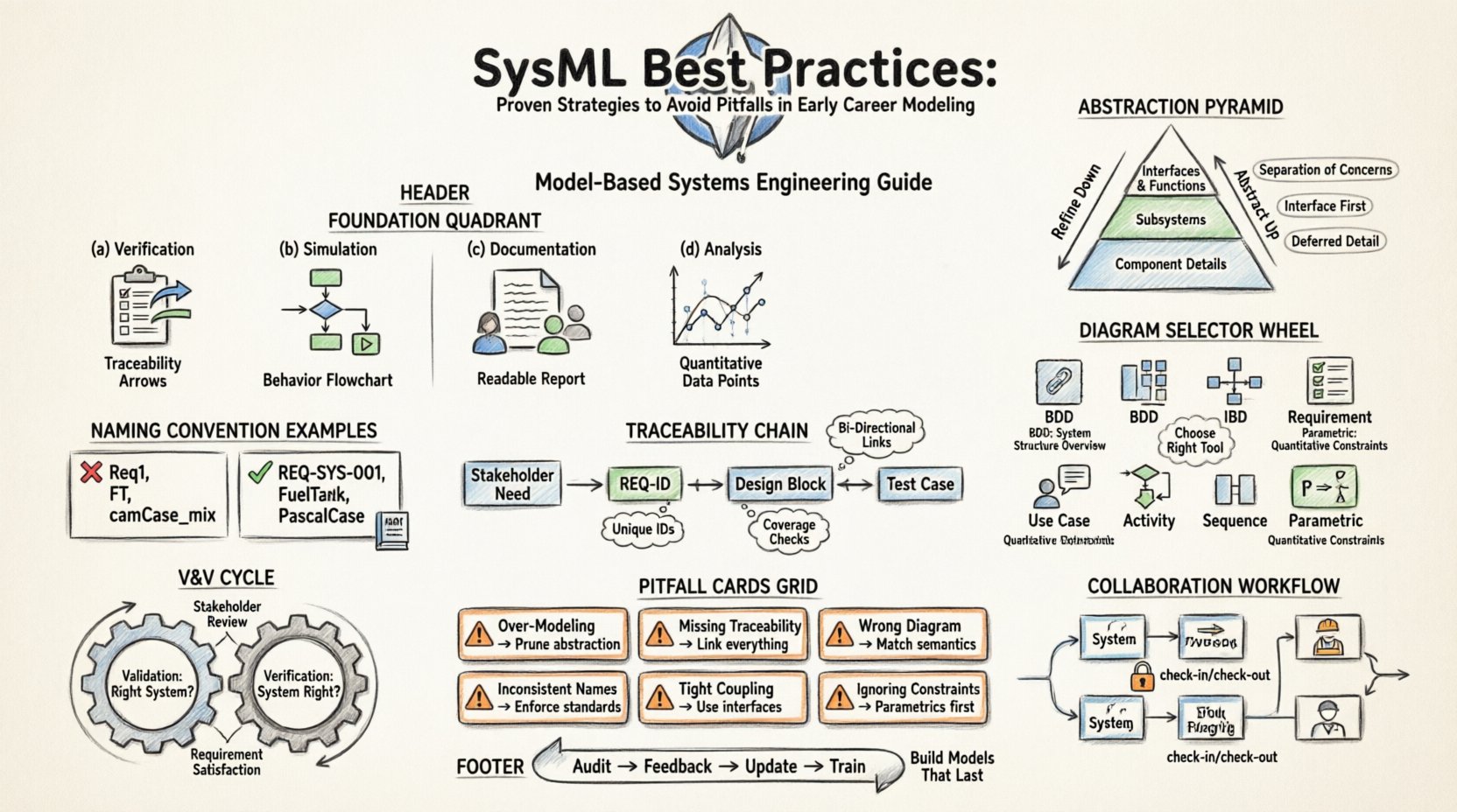
Before drawing a single block or defining a relationship, it is crucial to understand the purpose of the model. A model is not a drawing; it is a repository of structured information. When starting a new SysML project, the intent must be clear. Is the model intended for verification, simulation, documentation, or analysis? Each purpose dictates different modeling choices.
- Verification: Requires strict traceability and parameter constraints.
- Simulation: Needs behavior diagrams with sufficient detail for execution.
- Documentation: Focuses on clarity and readability for stakeholders.
- Analysis: Demands precise properties and quantitative data.
Skipping this definition phase often leads to bloated models that serve no specific function. A model that tries to do everything usually ends up doing nothing effectively. Align the model structure with the project’s specific engineering goals from day one.
🧠 Cultivating the Right Abstraction Mindset
One of the most frequent errors made by newcomers is attempting to model every detail immediately. Effective modeling relies on abstraction. You must decide what information is relevant at the current level of the system hierarchy and what can be deferred to a lower level.
Consider the hierarchy of your system. A top-level model should define interfaces and major functions without diving into internal component logic. As the project progresses, detail can be added through refinement.
Key Abstraction Principles
- Separation of Concerns: Keep requirements separate from physical design until necessary.
- Interface Focus: Define what a block does (interface) before defining how it does it (internal structure).
- Deferred Detail: Do not model internal ports and flows until the block is fully decomposed.
- Contextual Relevance: Only include elements that impact the current decision-making process.
When you include too much detail too early, the model becomes difficult to maintain. Changes at a lower level ripple upwards, causing unnecessary rework. By maintaining clear abstraction levels, you isolate changes and protect the integrity of the upper-level architecture.
📊 Selecting the Correct Diagram Type
SysML provides nine distinct diagram types. Using the right diagram for the right job is critical for communication. A common mistake is over-reliance on a single diagram type, such as the Block Definition Diagram (BDD), to represent the entire system. While BDDs are excellent for defining structure, they lack the ability to show flow and behavior clearly.
Here is a breakdown of when to utilize specific diagrams:
- Block Definition Diagram (BDD): Use for defining system hierarchy, parts, and interfaces. This is the structural backbone.
- Internal Block Diagram (IBD): Use to show how parts interact internally via connectors and ports.
- Requirement Diagram: Use to capture stakeholder needs and trace them to system elements.
- Use Case Diagram: Use to define system interactions with actors and high-level functions.
- Activity Diagram: Use for complex logic, algorithms, and data flow within a function.
- Sequence Diagram: Use to show time-ordered interactions between objects.
- Parametric Diagram: Use for mathematical constraints and performance analysis.
Do not force a complex behavior into a structure diagram. Conversely, do not attempt to define a physical hierarchy using only activity flows. Each diagram type has a specific semantic purpose. Adhering to these conventions ensures that anyone reading the model understands the intent without guessing.
🔗 Managing Requirements and Traceability
Requirements are the driver of systems engineering. In a model-based environment, requirements must be traceable to design elements. Without this link, the model becomes a static illustration rather than a dynamic engineering artifact. Traceability ensures that every requirement is satisfied by the design and every design element serves a requirement.
Establish a rigorous traceability strategy early in the project.
- Unique Identifiers: Assign unique IDs to all requirements. Avoid generic names like “Requirement 1”.
- Bi-Directional Links: Ensure links go from requirement to design and back.
- Coverage Analysis: Regularly check for orphaned requirements or unfulfilled design elements.
- Baseline Management: Lock requirements when they are approved to prevent scope creep.
Neglecting traceability is a critical failure point. If a requirement changes, you must know exactly which blocks, ports, or behaviors are affected. Without this visibility, change management becomes a manual, error-prone process. Automated traceability within the modeling environment is the standard for maintaining this integrity.
🏷️ Standardizing Naming Conventions
Consistency is the hallmark of a professional model. Inconsistent naming conventions lead to confusion, duplication, and difficulty in searching for elements. A naming convention should be defined at the start of the project and documented for the entire team.
Consider the following guidelines for your naming standards:
- Prefixes: Use prefixes to distinguish types (e.g., REQ for requirements, INT for interfaces).
- Case Sensitivity: Decide on camelCase, PascalCase, or snake_case and stick to it.
- Descriptive Names: Avoid abbreviations that are not universally understood. “Fuel Tank” is better than “FT” unless “FT” is defined in a glossary.
- Scope: Ensure names are unique within the model scope to avoid conflicts.
When team members join or leave, consistent naming allows new engineers to navigate the model quickly. It also facilitates automated checks and validation scripts. A chaotic naming scheme makes the model brittle and hard to scale.
🤝 Collaboration and Model Management
Systems engineering is rarely a solitary activity. Multiple engineers often work on different parts of the same model simultaneously. Without a structured approach to collaboration, version conflicts and data loss become inevitable.
Implement a clear workflow for model management:
- Check-in/Check-out: Restrict editing to one user at a time for specific packages to prevent conflicts.
- Version Control: Use version control systems to track changes over time.
- Modularization: Break the model into logical packages. Each engineer should own a specific package.
- Integration Points: Define clear interfaces between packages to minimize coupling.
Do not allow everyone to edit the root package. This creates a bottleneck and increases the risk of accidental overwrites. Modularization allows parallel development while maintaining a coherent system view. Regular integration sessions help identify interface mismatches before they become critical issues.
🚫 Common Pitfalls and Remediation Strategies
Even experienced engineers can slip into bad habits. Recognizing these patterns early can save weeks of rework. The table below outlines frequent modeling errors and the corrective actions required.
| Pitfall | Consequence | Remediation Strategy |
|---|---|---|
| Over-Modeling | Model becomes slow and difficult to maintain. | Review abstraction levels. Remove elements that do not serve a current requirement. |
| Missing Traceability | Inability to verify design compliance. | Run traceability reports. Link all design elements to requirements. |
| Incorrect Diagram Usage | Misinterpretation of system behavior. | Refer to diagram semantics. Use BDD for structure, Activity for flow. |
| Inconsistent Naming | Confusion and search failures. | Enforce naming conventions via validation rules or templates. |
| Tight Coupling | Changes in one area break others. | Use interfaces and ports. Minimize direct connections between blocks. |
| Ignoring Constraints | Design may violate physical limits. | Define constraints early using parametric diagrams or property constraints. |
🛠️ Validation and Verification in the Model
Building the model is only half the battle. You must validate that the model accurately represents the system and verify that the system meets the requirements. This distinction is vital.
- Validation: Are we building the right system? Does the model reflect the user’s needs?
- Verification: Are we building the system right? Does the design satisfy the requirements?
Incorporate validation checks into your modeling process. Review the model with stakeholders to ensure it matches their mental model of the system. Use verification checks to ensure all requirements are linked and satisfied. Do not wait until the end of the project to perform these checks. Integrate them into the weekly or sprint cycle.
📈 Continuous Improvement of the Model
A model is a living document. It evolves as the system evolves. Treating the model as a static artifact leads to obsolescence. Establish a routine for model maintenance.
- Regular Audits: Schedule periodic reviews to clean up unused elements.
- Feedback Loops: Encourage feedback from analysts and simulation engineers.
- Documentation Updates: Ensure model metadata matches current project status.
- Training: Keep the team updated on new modeling techniques and standards.
By committing to continuous improvement, the model remains a trusted source of truth. It becomes an asset that supports decision-making rather than a burden that hinders progress. This mindset shift is essential for long-term success in systems engineering.
🚀 Moving Forward with Confidence
Adopting these best practices requires discipline and patience. There will be moments where it seems faster to skip a step or take a shortcut. Resist this urge. The time saved in the short term is often lost in the long term through rework and confusion. SysML is a powerful tool, but its power is unlocked through disciplined application.
Focus on clarity, traceability, and consistency. Build models that communicate effectively and support rigorous engineering analysis. By avoiding the common pitfalls outlined in this guide, early career professionals can establish a strong foundation for their careers. The models you build today will inform the systems of tomorrow. Make them count.

