Systems engineering involves managing complex interactions between hardware, software, and human components. As systems grow in complexity, traditional documentation methods often fail to capture the necessary relationships and dependencies. This is where Systems Modeling Language (SysML) becomes essential. It provides a standardized way to describe, analyze, and design systems before physical construction begins.
This guide explores the core mechanics of SysML. It focuses on the practical application of modeling techniques to create clear, maintainable, and robust system architectures. The goal is to establish a solid foundation for understanding how structure, behavior, and requirements interact within a unified model.
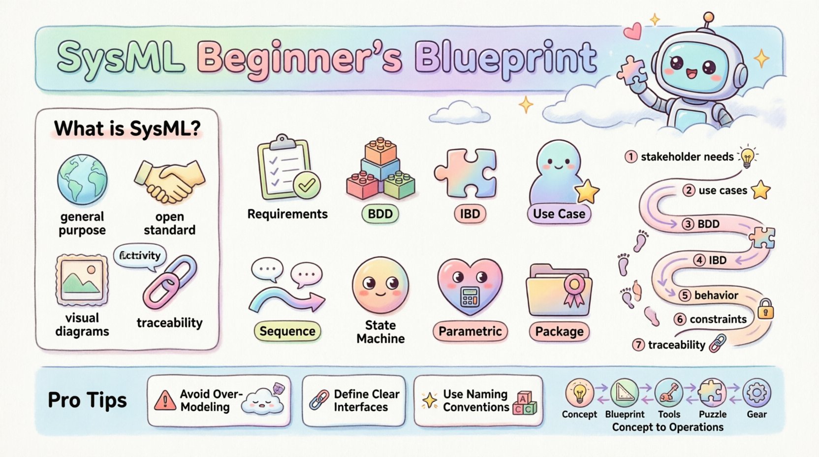
What is SysML? 🧩
SysML is a general-purpose modeling language for systems engineering applications. It is based on the Unified Modeling Language (UML) but extends it to accommodate the unique needs of hardware and software integration. Unlike UML, which focuses heavily on software, SysML supports the entire lifecycle of a system, from initial concept to disposal.
Key characteristics include:
- General Purpose: Applicable to mechanical, electrical, and software systems.
- Open Standard: Managed by the Object Management Group (OMG), ensuring vendor neutrality.
- Visual Representation: Uses diagrams to convey complex information intuitively.
- Traceability: Links requirements directly to design elements.
Why Model Systems? 🤔
Building complex systems without a model is akin to constructing a skyscraper without blueprints. Errors discovered during physical implementation are exponentially more expensive to fix than those found during the design phase. Modeling allows teams to:
- Identify conflicts early in the development cycle.
- Simulate performance and behavior before building.
- Communicate design intent clearly across multidisciplinary teams.
- Manage requirements and verify that the final product meets stakeholder needs.
The Core Diagrams of SysML 📊
SysML defines nine distinct diagram types. Each serves a specific purpose in capturing different aspects of the system. Understanding when to use which diagram is crucial for effective modeling.
| Diagram Type | Focus Area | Primary Use Case |
|---|---|---|
| Requirements Diagram | Requirements | Organizing and tracing requirements to system elements. |
| Block Definition Diagram (BDD) | Structure | Defining the system hierarchy and relationships between blocks. |
| Internal Block Diagram (IBD) | Structure | Showing internal connections, parts, and flows within a block. |
| Use Case Diagram | Behavior | Describing user interactions and functional goals. |
| Sequence Diagram | Behavior | Visualizing message exchanges over time between objects. |
| Activity Diagram | Behavior | Modeling the flow of control or data within a process. |
| State Machine Diagram | Behavior | Representing state transitions and reactions to events. |
| Parametric Diagram | Constraints | Defining mathematical constraints and performance equations. |
| Package Diagram | Structure | Organizing model elements into packages for management. |
Deep Dive: Structure Modeling 🔗
Structure modeling defines the static architecture of the system. It answers the question: “What is the system made of?” This is primarily handled through Blocks.
Block Definition Diagram (BDD) 🧱
The BDD is the backbone of the structural model. It defines the system hierarchy and the types of parts that make up the whole. A block represents a physical or logical component.
Key relationships in a BDD include:
- Aggregation: A “whole-part” relationship where the part can exist independently (e.g., an engine can exist outside a car).
- Composition: A strict ownership where the part cannot exist without the whole (e.g., a cylinder within an engine).
- Association: A connection between two blocks that does not imply ownership.
- Generalization: An inheritance relationship where a subclass inherits properties from a superclass.
When constructing a BDD, start with the top-level system block. Decompose this into subsystems, then components, and finally parts. This top-down approach ensures logical consistency.
Internal Block Diagram (IBD) ⚙️
While the BDD defines types, the IBD defines instances. It shows the internal composition of a specific block. This is where you define how data and signals flow between components.
Essential elements in an IBD:
- Parts: Instances of blocks defined in the BDD.
- Ports: Interfaces through which parts interact. Ports define the contract for communication.
- Flows: Connections between ports that carry data, signals, or material.
- Reference Properties: Links to external elements.
Using IBDs helps clarify interface definitions. By explicitly defining ports, you ensure that subsystems are decoupled and can be developed independently as long as they adhere to the interface contract.
Deep Dive: Behavior Modeling 🏃
Structure alone is insufficient. A system must also do something. Behavior modeling describes how the system functions over time and in response to stimuli.
Use Case Diagram 🎯
Use cases capture functional requirements from the perspective of an actor (user or external system). They define the “what” of the system.
Key concepts:
- Actors: Entities interacting with the system.
- Use Cases: Specific goals or functions.
- Includes/Extends: Relationships that show shared functionality or optional behaviors.
Sequence Diagram 📉
Sequence diagrams provide a detailed view of interactions over time. They are critical for defining the logic of operations.
Components of a sequence diagram:
- Lifelines: Represent the participants in the interaction.
- Messages: Arrows indicating communication between lifelines.
- Activation Bars: Indicate when a participant is actively processing a message.
- Combined Fragments: Loops, alternatives, and parallel processing.
When creating sequence diagrams, focus on the happy path first. Then, branch out to handle error conditions and exceptions. This ensures the model is robust.
Activity Diagram 🔄
Activity diagrams model the flow of control or data. They are similar to flowcharts but support concurrent processing and object flows.
Use cases for activity diagrams:
- Complex business processes.
- Algorithmic logic within a component.
- Data flow between subsystems.
Requirements Engineering 📝
One of the most powerful features of SysML is the ability to link requirements directly to the model. This creates a traceability matrix that is visual and interactive.
Requirements Diagram 📋
This diagram organizes requirements hierarchically. It allows you to define a system requirement and then derive sub-requirements for subsystems.
Traceability relationships include:
- Satisfy: A design element satisfies a requirement.
- Verify: A test case verifies a requirement.
- Derive: One requirement is derived from another.
- Refine: A requirement is elaborated into more detail.
By maintaining these links, teams can perform impact analysis. If a requirement changes, the model highlights all affected design elements. This reduces the risk of regression errors.
Parametric Modeling and Constraints 📐
Systems often have performance constraints that must be mathematically verified. Parametric diagrams allow you to define equations and constraints directly within the model.
Key elements:
- Constraint Blocks: Definitions of mathematical relationships (e.g., Force = Mass × Acceleration).
- Constraint Properties: Instances of constraint blocks attached to model elements.
- Connectors: Links between constraint properties and model properties.
This capability enables system analysis without leaving the modeling environment. You can solve for unknown variables or verify that a design meets safety margins.
Building the Architecture: A Process Flow 🛠️
Effective modeling follows a structured process. Jumping straight into drawing diagrams often leads to inconsistent models. Follow this workflow for better results:
- Define Stakeholder Needs: Gather the high-level requirements and goals.
- Create a Use Case Diagram: Map out the functional scope.
- Develop the Block Definition Diagram: Establish the system hierarchy.
- Detail Internal Block Diagrams: Define interfaces and internal connections.
- Model Behavior: Create sequence and activity diagrams for key functions.
- Apply Parametric Constraints: Define performance boundaries.
- Trace Requirements: Link every design element back to a requirement.
Common Pitfalls and Best Practices ⚠️
Even experienced modelers face challenges. Avoiding common mistakes saves time and improves model quality.
Pitfall 1: Over-Modeling
Creating every possible diagram for every detail leads to a bloated model that is hard to maintain. Focus on the information needed for decision-making. Use abstraction to hide detail where it is not immediately relevant.
Pitfall 2: Ignoring Interfaces
Interfaces are the contract between components. If ports and flows are not defined clearly, integration will fail. Ensure all external connections are explicit.
Pitfall 3: Mixing Levels of Abstraction
Do not mix logical architecture (what the system does) with physical architecture (what the system is made of) in the same diagram unless necessary. Keep them distinct to avoid confusion.
Best Practice: Naming Conventions
Consistent naming is vital for readability. Use a standard format for blocks, ports, and requirements. For example, prefix requirements with “REQ-” and blocks with “BLK-“. This helps in filtering and searching.
Best Practice: Version Control
Models evolve. Ensure your modeling environment supports version control. Track changes to requirements and design elements to maintain a history of decisions.
The Role of Modeling in Systems Engineering Lifecycle 🔄
SysML is not a one-time activity. It supports the entire lifecycle:
- Concept Phase: High-level BDDs to explore trade-offs.
- Definition Phase: Detailed IBDs and behavior diagrams to specify the design.
- Development Phase: Use cases to guide software and hardware development.
- Integration Phase: Traceability to verify compliance with requirements.
- Operations Phase: Documentation of the as-built system for maintenance.
This continuity ensures that the model remains a source of truth throughout the project. It prevents the common issue where documentation becomes outdated as soon as development begins.
Integration with Other Standards 🔗
SysML does not exist in isolation. It often integrates with other standards depending on the industry.
- ISO 26262: Automotive safety standards often require model-based design.
- DO-178C: Aerospace software certification relies on traceability.
- IEEE 1471: Architecture descriptions can be mapped to SysML views.
Understanding these connections helps in aligning the model with regulatory requirements. SysML acts as the bridge between high-level system goals and low-level implementation details.
Conclusion on System Modeling 🚀
Adopting SysML requires a shift in mindset from document-centric to model-centric. It demands discipline in maintaining links and consistency. However, the payoff is a system architecture that is robust, verifiable, and clear.
By focusing on structure, behavior, and requirements, teams can reduce risk and improve collaboration. The investment in learning these modeling techniques pays dividends in reduced rework and higher quality outcomes.
Start small. Model a single subsystem. Establish the links. Expand gradually. With practice, the complexity of the model will become a manageable asset rather than a burden.

