In the complex ecosystem of software engineering, clarity is currency. When teams build systems that scale, they require a blueprint that transcends mere code snippets. The Unified Modeling Language (UML) class diagram serves as this essential architectural artifact. It provides a static view of the system structure, detailing how objects interact, inherit, and collaborate. This guide explores the function of these diagrams throughout the Software Development Life Cycle (SDLC), ensuring robust design and maintainable codebases.
🔄 Integrating UML Class Diagrams Across SDLC Phases
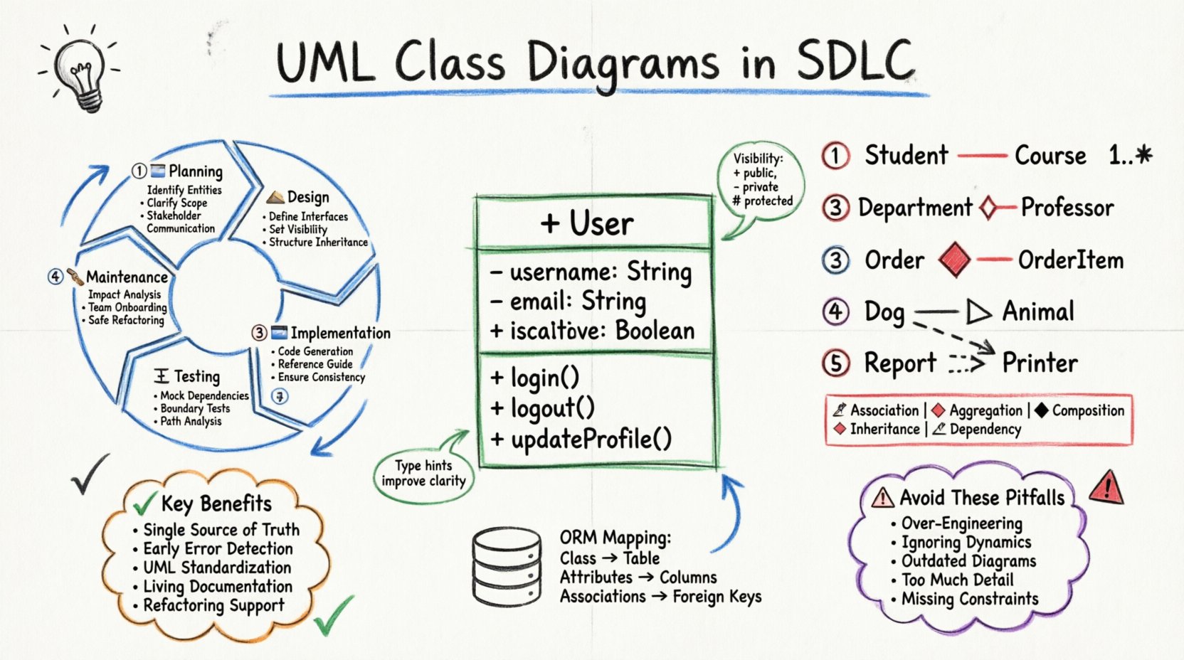
The Software Development Life Cycle is not a linear sprint but a series of iterative phases. A class diagram is not created once and discarded; its utility shifts as the project matures. Understanding where and why these diagrams appear at each stage prevents documentation rot and ensures alignment between design intent and implementation.
📝 Planning and Requirements Analysis
During the initial planning phase, stakeholders define what the system must do. While use cases describe behavior, class diagrams begin to capture the nouns of the system. They help identify the entities that will hold data and perform actions. This early visualization helps stakeholders understand the scope without getting bogged down in syntax.
- Identifying Entities: Determining the core objects required (e.g., User, Product, Transaction).
- Clarifying Scope: Visualizing boundaries helps prevent scope creep by showing what is in or out of the model.
- Communication: Non-technical stakeholders can review these diagrams to confirm business rules regarding object relationships.
🏗️ System Design and Architecture
This is the primary home of the UML class diagram. Architects define the structure, visibility, and relationships between components. The focus shifts from “what” to “how”. Detailed attributes and methods are specified. Design patterns such as Singleton, Factory, or Strategy are often represented through the structural relationships defined here.
- Defining Interfaces: Abstract classes and interfaces are formalized to ensure loose coupling.
- Defining Visibility: Public, private, and protected members are assigned to enforce encapsulation.
- Structuring Inheritance: Hierarchies are established to promote code reuse and polymorphism.
💻 Implementation and Coding
Developers use the finalized diagrams as a reference while writing code. While modern IDEs can generate code from models, the diagram often serves as the source of truth for complex logic. It ensures that the implementation adheres to the architectural contract.
- Code Generation: Skeleton code can be generated to save setup time.
- Reference Guide: Developers consult the diagram when unsure about a dependency or relationship.
- Consistency: Ensures all developers follow the same structural standards.
🧪 Testing and Quality Assurance
QA engineers utilize class diagrams to understand the system’s internal state. This aids in creating unit tests and integration tests. Knowing the dependencies between classes allows testers to mock objects accurately.
- Mocking Dependencies: Diagrams show which classes depend on others, guiding the creation of test doubles.
- Boundary Testing: Attribute definitions help define valid and invalid input ranges.
- Path Analysis: Method signatures indicate entry points for testing logic flows.
🛠️ Maintenance and Evolution
Software rarely stays static. As requirements change, the class diagram must evolve. A maintained diagram acts as a map for refactoring. Without it, developers risk introducing technical debt by modifying code without understanding the ripple effects on other components.
- Impact Analysis: Changes to a base class are visible in the inheritance structure.
- Onboarding: New team members can understand the system architecture quickly.
- Refactoring: Identifying god classes or high coupling becomes easier with a visual map.
🧱 Core Components of a Class Diagram
To use these diagrams effectively, one must understand the building blocks. Each rectangle in the diagram represents a class, divided into distinct sections that convey specific information.
🏷️ The Class Name
The top section contains the class name. It should be a noun, representing a concept within the domain. Naming conventions should be consistent, typically using PascalCase. The name defines the identity of the object in the system.
📥 Attributes (Fields)
The middle section lists the properties of the class. These represent the state. Each attribute includes visibility, name, and type.
- Visibility: Indicated by symbols like
+(public),-(private), or#(protected). - Type: Specifies the data type (e.g., String, Integer, Boolean).
- Multiplicity: May indicate if an attribute can hold multiple values or a single value.
⚙️ Methods (Operations)
The bottom section details the behavior. These are functions or procedures that the class can perform. Similar to attributes, methods have visibility and return types.
- Encapsulation: Methods control how attributes are accessed or modified.
- Logic: They contain the business logic associated with the class.
- Parameters: Arguments passed to the method define how it interacts with external inputs.
🔗 Understanding Relationships and Associations
Classes rarely exist in isolation. The lines connecting them describe how they interact. These relationships define the structural integrity of the system. Misinterpreting a relationship can lead to fragile code that breaks under load or change.
🔗 Associations
An association represents a structural relationship where objects are linked. It implies that one class knows about another. For example, a Student is associated with a Course.
- Cardinality: Defines how many instances are involved (e.g., 1-to-1, 1-to-many).
- Role Names: Labels on the line clarify the nature of the link.
- Navigation: Indicates the direction of the relationship.
🔗 Aggregation vs. Composition
Both represent “has-a” relationships, but the lifecycle management differs significantly. This distinction is critical for memory management and resource allocation.
🔗 Inheritance
Also known as generalization, this represents an “is-a” relationship. A subclass inherits attributes and methods from a superclass. This promotes reuse and establishes a hierarchy.
- Polymorphism: Allows objects of different subclasses to be treated as objects of a common superclass.
- Extensibility: New types can be added without modifying existing code.
🔗 Dependency
A dependency is a weaker relationship. It implies that a change in one class may affect another. For example, a class might use another class as a parameter in a method.
📊 Relationship Types Comparison
| Relationship | Symbol | Meaning | Lifecycle Impact |
|---|---|---|---|
| Association | Line | Structural link | Independent lifecycles |
| Aggregation | Line + Diamond (Empty) | Whole-Part (Weak) | Part survives Whole |
| Composition | Line + Diamond (Filled) | Whole-Part (Strong) | Part dies with Whole |
| Inheritance | Line + Triangle | Is-A relationship | Subclass depends on Superclass |
| Dependency | Dashed Line + Arrow | Uses relationship | Temporary usage |
🗄️ Bridging Design and Database
One of the most practical applications of the UML class diagram is mapping to data storage. While class diagrams represent objects in memory, databases represent tables in storage. The transition between these two worlds requires careful planning.
- Table Mapping: Each class typically maps to a database table.
- Primary Keys: Attributes designated as unique identifiers become primary keys.
- Foreign Keys: Associations are translated into foreign key constraints to maintain referential integrity.
- Normalization: The diagram helps identify redundant data that should be moved to separate tables.
- ORM Configuration: Object-Relational Mapping tools rely on the structure defined in the diagram to generate SQL queries automatically.
When designing the diagram, consider the performance implications of the relationships. A one-to-many relationship in a diagram might result in a join operation that impacts query speed. Proper modeling at this stage prevents database bottlenecks later.
✅ Advantages of Visual Modeling
Why invest time in creating these diagrams? The return on investment comes from reduced ambiguity and higher code quality.
- Single Source of Truth: The diagram serves as a reference that aligns the entire team.
- Early Detection of Errors: Logical flaws are easier to spot in a diagram than in thousands of lines of code.
- Standardization: UML is a standard language. Developers from different backgrounds can understand the model.
- Documentation: It creates living documentation that survives the developers who wrote the code.
- Refactoring Support: When restructuring code, the diagram helps predict side effects.
⚠️ Common Modeling Pitfalls
Even experienced architects make mistakes. Avoiding these traps ensures the diagram remains useful.
- Over-Engineering: Creating diagrams for every small utility class adds noise. Focus on core domain objects.
- Ignoring Dynamics: Class diagrams are static. They do not show state changes over time. Use sequence diagrams for flow.
- Outdated Documentation: If the code changes and the diagram does not, the diagram is a liability.
- Too Much Detail: Do not list every single getter and setter. Focus on the business logic methods.
- Ignoring Constraints: Failure to note multiplicity or cardinality constraints leads to runtime errors.
🛠️ Keeping Diagrams Current
Maintaining the fidelity of the diagram is an ongoing task. In agile environments, this can be challenging due to rapid changes.
- Round-Trip Engineering: Use tools that sync code and diagrams automatically. Changes in code update the diagram and vice versa.
- Diagram as Code: Some teams prefer defining models in text files that are compiled into diagrams, making version control easier.
- Regular Reviews: Include diagram updates in the definition of done for user stories.
- Focus on Stability: Update diagrams when the core architecture changes, not for every minor bug fix.
🚀 Moving Forward
The UML class diagram is a foundational tool for structuring software systems. It bridges the gap between abstract requirements and concrete implementation. By adhering to best practices and maintaining the diagrams throughout the lifecycle, teams can build systems that are robust, scalable, and easier to maintain. The investment in clear modeling pays dividends in reduced bugs and faster development cycles over the long term.
As you apply these concepts, remember that the goal is clarity. The diagram should illuminate the system, not obscure it. With a disciplined approach to modeling, your architecture will stand the test of time and change.

