Modern software ecosystems often accumulate decades of development history. When new teams inherit these systems, they face a complex web of interconnected logic, undocumented behaviors, and evolving architecture. This is the reality of legacy code. Understanding it is not optional; it is a prerequisite for safe modification and sustainable growth. Reverse engineering legacy code with UML class diagrams provides a structured path to clarity. It transforms opaque source files into understandable visual models that reveal how the system actually functions.
This guide details the methodology for analyzing existing codebases and constructing accurate UML class diagrams. We explore the technical steps, the theoretical underpinnings, and the practical benefits of visualizing object-oriented structures. By the end, you will have a clear framework for tackling even the most intricate legacy environments.
Why Legacy Systems Require Visual Analysis 🕰️
Legacy code often suffers from a lack of documentation. Over time, the original developers leave, and the context behind specific design decisions fades. The code remains, but the reasoning becomes obscure. Relying solely on reading source code can be inefficient and prone to misinterpretation. Visual models offer a higher-level abstraction.
Consider the following reasons why visual analysis is critical:
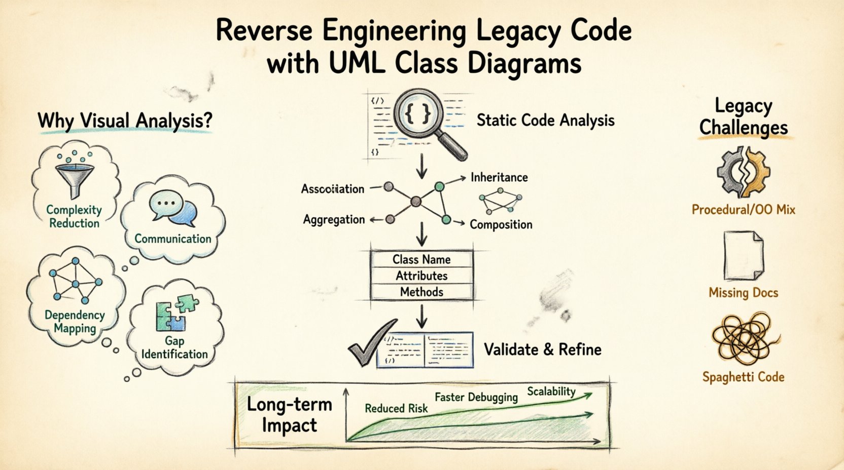
- Complexity Reduction: Large codebases contain thousands of lines of logic. A diagram condenses this into manageable relationships and entities.
- Communication: Stakeholders and new team members understand diagrams faster than raw syntax. They provide a common language for discussing architecture.
- Dependency Mapping: Legacy systems often have hidden dependencies. Visualizing these helps prevent regression errors during refactoring.
- Gap Identification: Comparing the existing code to the intended design highlights deviations and technical debt.
Without a visual representation, changes are risky. You might modify one class without realizing it breaks a critical link in another module. Diagrams act as a safety net, showing the full scope of impact before a single line of code is changed.
Understanding UML Class Diagram Fundamentals 📐
Unified Modeling Language (UML) is a standard notation for visualizing system design. The class diagram is the most common type used for reverse engineering. It describes the static structure of the system by displaying classes, their attributes, operations, and the relationships among objects.
When extracting this information from code, you focus on specific elements:
- Class Name: Represents a specific entity or concept within the domain. In code, this maps directly to a class definition.
- Attributes: Data stored within the class. These correspond to member variables or properties.
- Methods: Behaviors or functions the class can perform. These map to functions or methods defined in the source.
- Relationships: Connections between classes that define how they interact.
The goal is not to recreate the code line-for-line, but to capture the architectural intent. This abstraction allows you to see patterns rather than individual syntax details.
The Reverse Engineering Workflow 🔁
Constructing a diagram from raw code is a systematic process. It requires analysis, extraction, and validation. There is no single tool that automates this perfectly for every scenario, so human oversight is essential. The following workflow ensures accuracy and completeness.
Step 1: Static Code Analysis
Begin by scanning the codebase without executing it. Static analysis tools can parse the structure to identify classes, methods, and variable types. This step provides the raw data needed for the diagram.
- Identify all class definitions.
- List public, private, and protected members.
- Map imports and external dependencies.
This phase creates a list of entities. You do not need to understand the logic yet, just the existence and signature of the components.
Step 2: Identify Relationships
Once classes are listed, determine how they connect. Look for instantiation, inheritance, and usage patterns. This is the core of the diagram. The relationships define the flow of control and data.
Common relationship types include:
- Association: A general link between objects. One object uses another.
- Inheritance: A specialized “is-a” relationship where one class extends another.
- Aggregation: A “has-a” relationship where the part can exist independently of the whole.
- Composition: A stronger “has-a” relationship where the part cannot exist without the whole.
Step 3: Map to Visual Model
Transfer the identified elements into a drawing environment. Place classes as boxes and relationships as lines. Ensure cardinality is noted where applicable (e.g., one-to-many). This visual representation is your working hypothesis of the system.
Step 4: Validate and Refine
Review the diagram against the code. Does every method in the code appear in the diagram? Are all relationships accurate? If the code has been modified frequently, the diagram might be outdated. Validate by tracing a few execution paths through the code and the diagram to ensure they match.
| Workflow Phase | Key Action | Output |
|---|---|---|
| Static Analysis | Parse source files | List of classes and members |
| Relationship Mapping | Trace dependencies | Defined connections between classes |
| Visual Construction | Draw diagram | Initial UML model |
| Validation | Code-to-diagram check | Verified architecture model |
Key Relationships to Identify 🕸️
Understanding the nature of connections is vital for accurate reverse engineering. Misinterpreting a relationship can lead to incorrect assumptions about system behavior. Here is a deeper look at how to identify these in code.
Inheritance (Generalization)
Look for keywords indicating extension or implementation. In many object-oriented languages, this is explicit. A parent class defines common behavior, while child classes specialize it.
- Check for base class references in class definitions.
- Identify overridden methods in subclasses.
- Trace the hierarchy from the most generic to the most specific.
This structure is often a sign of good design, but in legacy code, it can become deep and convoluted. Ensure the inheritance chain makes logical sense.
Association and Dependency
These are often the most common links. An association exists when one class holds a reference to another. A dependency is a temporary relationship, such as a method parameter.
- Check constructor arguments to see which classes are required.
- Look for method parameters that indicate usage.
- Identify member variables that hold references to other classes.
Distinguishing between a strong association and a temporary dependency is important. Strong associations imply the classes are tightly coupled, while dependencies suggest looser interaction.
Common Challenges in Legacy Environments ⚠️
Legacy code does not always follow modern design patterns. You may encounter structural irregularities that make diagramming difficult. Recognizing these challenges helps you adapt your approach.
Procedural Code in Object-Oriented Systems
Many systems evolve over time. A project might start as procedural and shift to object-oriented. This results in code that mixes styles. You might find global functions acting as classes, or classes with no meaningful behavior.
- Treat procedural modules as standalone components.
- Do not force them into class structures if they do not fit.
- Document them as functional blocks rather than objects.
Lack of Comments and Naming Conventions
Old codebases often lack documentation. Variable names may be abbreviated or inconsistent. This makes it hard to infer the purpose of a class.
- Look at method names for clues about functionality.
- Trace data flow to understand what a variable holds.
- Use context from surrounding code to infer meaning.
Spaghetti Code and Tight Coupling
Over time, classes can become entangled. Changing one might break another in an unexpected way. This makes the dependency graph dense and hard to read.
- Focus on high-level modules first to simplify the view.
- Use color coding to highlight tightly coupled groups.
- Identify interfaces or abstraction layers that separate concerns.
From Diagram to Documentation 📝
The ultimate output of this process is documentation that aids future development. A UML class diagram is not just a picture; it is a specification of the system’s structure. This documentation serves multiple purposes.
Onboarding: New developers can study the diagram to understand the architecture before reading specific files. This reduces the time required to become productive.
Refactoring Planning: Before making changes, the diagram helps identify which classes are affected. It acts as a roadmap for safe modifications.
Communication: When discussing system changes with management or clients, the diagram provides a clear visual aid that technical jargon cannot convey.
Ensure the documentation is kept current. If the code changes, the diagram should be updated. An outdated diagram is worse than no diagram at all, as it creates false confidence.
Best Practices for Accuracy ✅
To maintain the integrity of the reverse engineering effort, follow these guidelines. Consistency and rigor are key.
- Start High Level: Begin with the main subsystems. Do not get bogged down in details immediately. Define the major components first.
- Use Standard Notation: Stick to standard UML symbols. This ensures anyone familiar with the standard can read the diagram without confusion.
- Validate with Code Walkthroughs: Regularly step through code execution to verify the diagram matches reality.
- Document Assumptions: If you are unsure about a relationship, note it. Do not guess. Mark uncertain areas for later review.
- Iterate: Reverse engineering is rarely a one-time task. As you understand the system better, refine the diagram.
Long-term Maintenance Impact 📈
Investing time in reverse engineering yields long-term dividends. It reduces technical debt by making the system transparent. When the architecture is clear, it is easier to identify areas that need improvement.
Reduced Risk: With a clear map of dependencies, the risk of breaking the system during updates decreases significantly. You know exactly what will be affected.
Faster Debugging: When errors occur, the diagram helps trace the flow of data. You can see which class is responsible for a specific action.
Scalability: Understanding the current structure allows you to plan for growth. You can identify bottlenecks and design new components that fit the existing architecture.
Legacy code is often viewed as a burden. However, with the right tools and methodology, it becomes an asset. UML class diagrams bridge the gap between the old code and new understanding. They transform mystery into knowledge.
Conclusion of the Process 🎯
Reverse engineering legacy code is a disciplined task. It requires patience, attention to detail, and a solid understanding of software architecture. By using UML class diagrams, you create a living document that evolves with the system. This approach ensures that the knowledge embedded in the code is preserved and accessible.
Start with the basics. Identify the classes. Map the relationships. Validate the model. This systematic approach leads to a clearer understanding of the system. It empowers teams to maintain, update, and extend the software with confidence. The effort invested in visualization pays off in stability and maintainability.
Remember that the goal is clarity, not perfection. A diagram that is 90% accurate is often more useful than one that is incomplete. Focus on the critical paths and major components. Use the diagram as a tool for thinking, not just a static artifact. As the system changes, so should your understanding. Keep the documentation aligned with the code.
By following these steps, you turn a legacy challenge into a manageable engineering task. The code becomes readable. The architecture becomes transparent. The future of the system becomes secure.

