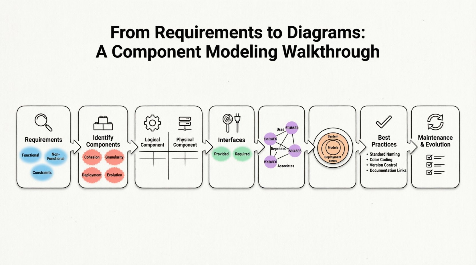
Building robust software systems requires more than just writing code. It demands a clear understanding of how different parts fit together. Component modeling serves as the blueprint for this structure. It bridges the gap between abstract business needs and concrete implementation details. This guide walks through the process of translating requirements into actionable diagrams.
🔍 The Foundation: Understanding Requirements
Before drawing a single box, you must understand what the system needs to do. Requirements form the bedrock of any architectural decision. They define the scope, constraints, and expected behaviors. Ignoring this step often leads to diagrams that look good but do not solve the actual problem.
Here is how to approach the requirements phase:
- Functional Requirements: These describe specific actions the system must perform. For example, “The system shall process payment transactions within two seconds.”
- Non-Functional Requirements: These cover quality attributes like performance, security, and scalability. Examples include “The system must handle 10,000 concurrent users.”
- Constraints: Limitations imposed by technology, budget, or regulation. A constraint might be “Data must reside in a specific geographic region.”
When analyzing these inputs, look for keywords that suggest distinct capabilities. Words like “process,” “store,” “verify,” or “notify” often point toward distinct components. Grouping related functionalities helps in identifying boundaries.
🧱 Identifying Components
A component represents a modular part of the system that encapsulates functionality. It is a unit of implementation that can be replaced independently. Unlike a class, which is code-level, a component is an architectural abstraction.
Criteria for Component Identification
Deciding what constitutes a component requires judgment. Consider the following factors:
- Cohesion: Does the component handle a single responsibility? High cohesion is preferred.
- Granularity: Is the component too small to be useful on its own? Or is it too large and complex? Aim for a middle ground.
- Deployment: Can this unit be deployed independently? If yes, it is a strong candidate for a component.
- Evolution: Will this part change more frequently than others? Isolating volatile parts reduces risk.
Logical vs. Physical Components
Not all components are created equal. Distinguishing between logical and physical views is crucial for clarity.
| Aspect | Logical Component | Physical Component |
|---|---|---|
| Focus | Functionality and behavior | Deployment and infrastructure |
| Example | Order Processing Service | Web Server Instance |
| Dependency | Other logical services | Hardware or network resources |
| Use Case | System design and planning | DevOps and infrastructure setup |
🔌 Defining Interfaces
Components do not work in isolation. They communicate through interfaces. An interface defines a contract that a component fulfills or requires. It separates the “what” from the “how.” This separation allows teams to work on different parts without breaking the whole.
Provided vs. Required Interfaces
Every component has two types of interaction points:
- Provided Interface (Lollipop): This shows what the component offers to the outside world. If a component provides a “Login Service” interface, other components can use it without knowing the internal logic.
- Required Interface (Socket): This shows what the component needs to function. If a “Dashboard” component requires a “User Data” interface, it depends on another component to supply that data.
When modeling, clearly label these interfaces. Ambiguity here leads to integration issues later. Ensure that the interface name matches the business capability it represents.
🔗 Establishing Relationships
Once components and interfaces are defined, you must map the connections between them. These relationships dictate data flow and control flow. They reveal the dependencies that drive system complexity.
Types of Dependencies
Use the following relationships to connect your elements:
- Uses: One component relies on the functionality of another. This is a direct dependency.
- Realizes: A component implements an interface provided by another. This often links a component to an interface.
- DependsOn: A high-level dependency indicating that the existence of one component affects another.
- Associates: A loose connection indicating that components interact but do not strictly own each other.
Be careful with the number of connections. A component with too many incoming and outgoing lines becomes a bottleneck. This is known as a “hub” component. Try to distribute dependencies evenly across the architecture.
📏 Managing Granularity
One of the most common challenges in component modeling is determining the right level of detail. If the diagram is too coarse, it provides no value. If it is too fine, it becomes cluttered and unreadable.
Levels of Abstraction
Consider using multiple views of the same system at different levels:
- System View: Shows major subsystems and their external interfaces. Good for high-level stakeholders.
- Module View: Breaks down subsystems into smaller functional groups. Useful for development teams.
- Deployment View: Shows where components run. Crucial for operations and infrastructure teams.
Do not try to fit every detail into one diagram. Instead, create a hierarchy. Link high-level diagrams to detailed ones using reference markers. This keeps the primary view clean while allowing deep dives when necessary.
🛠 Best Practices for Modeling
Consistency is key to maintaining architecture documentation over time. Follow these guidelines to ensure your diagrams remain useful.
| Practice | Description | Benefit |
|---|---|---|
| Standard Naming | Use clear, descriptive names for all components. | Reduces confusion among team members. |
| Color Coding | Use colors to indicate status or type (e.g., green for active, red for deprecated). | Visual cues speed up comprehension. |
| Version Control | Track changes to the diagram over time. | Ensures the model matches the codebase. |
| Documentation Links | Include references to detailed specifications. | Provides context without cluttering the visual. |
🚫 Common Pitfalls to Avoid
Even experienced architects can make mistakes. Being aware of common errors helps you refine your approach.
- Over-Engineering: Creating complex diagrams for simple systems. Start simple and add complexity only when needed.
- Ignoring Non-Functional Needs: Focusing only on features and forgetting security or performance constraints.
- Static Modeling: Treating the diagram as a one-time task. Systems evolve, and diagrams must evolve with them.
- Code-Level Detail: Drawing class structures instead of component structures. Components should represent logical boundaries, not just code files.
🔄 Maintenance and Evolution
A component diagram is a living document. As the system grows, the diagram must change. This requires a process for updates.
Change Management
When a requirement changes, ask how it impacts the architecture. Does it require a new component? Does it modify an existing interface? If the answer is yes, update the diagram immediately. Delaying updates creates a drift between the design and the reality.
Regular reviews are essential. Schedule periodic sessions where the architecture team walks through the diagrams. Check for:
- Broken dependencies.
- Orphaned components that are no longer used.
- Interfaces that have become too complex.
- Security gaps in the data flow.
📊 Integrating with Other Models
Component diagrams do not exist in a vacuum. They work best when integrated with other modeling artifacts.
- Sequence Diagrams: Use sequence diagrams to show how components interact over time. They complement the static structure of component diagrams.
- State Diagrams: Use these to model the internal lifecycle of a specific component.
- Deployment Diagrams: Link component diagrams to deployment diagrams to show physical hosting.
This holistic approach ensures that the system is designed correctly from every angle. It prevents silos where the code works, but the infrastructure does not support it.
📝 Final Thoughts on Modeling
The goal of component modeling is clarity. It is about communicating intent to the team and stakeholders. A well-crafted diagram reduces ambiguity and accelerates development. It serves as a shared language for everyone involved in the project.
Remember that the diagram is a tool, not the end product. Its value lies in the conversations it sparks. Use it to identify risks, plan work, and align expectations. As you refine your skills, you will find that the diagrams become more accurate and useful over time.
Start with your requirements. Identify your boundaries. Define your contracts. Connect your parts. Review your work. This cycle ensures a solid foundation for your software architecture.

