Understanding the architecture of a software system begins with clear visualization. UML Class Diagrams serve as the blueprint for object-oriented programming. They define the structure, behavior, and relationships within a system before a single line of code is written. This guide provides a comprehensive overview of how to construct these diagrams effectively, ensuring clarity and maintainability throughout the development lifecycle.
What is a UML Class Diagram? 🏗️
A Unified Modeling Language (UML) Class Diagram is a static structure diagram that describes the structure of a system by showing the system’s classes, their attributes, operations (or methods), and the relationships among objects. Unlike sequence diagrams which show behavior over time, class diagrams focus on the what rather than the when.
- Static View: It represents the system at a specific point in time.
- Structural View: It outlines the components and their connections.
- Foundation: It is the most widely used diagram in the UML suite for object-oriented design.
By visualizing the data and logic together, developers can identify potential issues regarding data integrity, coupling, and cohesion early in the process.
Core Components of a Class 📦
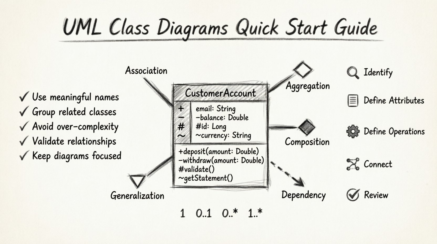
Every element in a class diagram must be precise. A class is typically represented as a rectangle divided into three compartments. Each compartment serves a distinct purpose in defining the class’s identity and capabilities.
1. The Class Name Compartment
The top section contains the name of the class. This should be a noun, reflecting the entity being modeled.
- Capitalization: Use PascalCase (e.g.,
CustomerAccount). - Abstract Classes: If the class cannot be instantiated directly, italicize the name (e.g., Animal).
- Interfaces: Often denoted with the stereotype
<<interface>>.
2. The Attributes Compartment
The middle section lists the properties or data members of the class. This defines the state of the object.
- Data Types: Specify the type (e.g.,
String,Integer,Date). - Visibility: Use symbols to indicate access levels (see table below).
- Initial Values: You may include default values (e.g.,
isActive = true).
3. The Operations Compartment
The bottom section lists the methods or functions that the class can perform. This defines the behavior.
- Method Names: Use camelCase (e.g.,
calculateTotal()). - Parameters: Include input arguments and their types within parentheses.
- Return Types: Specify the output type after a colon (e.g.,
: Double).
Visibility Modifiers Table 👁️
| Symbol | Visibility | Description |
|---|---|---|
+ |
Public | Accessible from any class. |
- |
Private | Accessible only within the class itself. |
# |
Protected | Accessible within the class and its subclasses. |
~ |
Package | Accessible within the same package or namespace. |
Understanding Relationships 🔗
Classes rarely exist in isolation. They interact through relationships. Understanding the nuance between different types of links is critical for accurate modeling. There are five primary relationship types used in class diagrams.
1. Association
An association represents a structural link between two classes. It implies that an object of one class may be aware of an object of another class. It is often a bidirectional link unless specified otherwise.
- Example: A
Doctortreats aPatient. - Direction: Can be one-way or two-way.
- Labeling: Relationships should have meaningful names (e.g.,
manages,employs).
2. Aggregation
Aggregation is a specialized form of association representing a whole-part relationship. However, the part can exist independently of the whole. It is often described as a “Has-A” relationship.
- Example: A
DepartmenthasEmployees. If the department dissolves, the employees still exist. - Symbol: A hollow diamond at the whole end of the line.
3. Composition
Composition is a stronger form of aggregation. It implies exclusive ownership. The part cannot exist without the whole. If the whole is destroyed, the parts are destroyed with it.
- Example: A
HousecontainsRooms. If the house is demolished, the rooms cease to exist as part of that house. - Symbol: A solid diamond at the whole end of the line.
- Lifecycle: The lifecycle of the part is dependent on the lifecycle of the whole.
4. Generalization (Inheritance)
This relationship represents an is-a hierarchy. It allows a child class to inherit attributes and methods from a parent class. This promotes code reuse and polymorphism.
- Example: A
Truckis aVehicle. - Symbol: A solid line with a hollow triangle pointing to the parent class.
- Usage: Use sparingly to avoid deep inheritance trees that become hard to maintain.
5. Dependency
A dependency indicates that a change in the specification of one class may affect another. It is a weaker relationship than association. It often implies a temporary usage of one object by another.
- Example: A
ReportGeneratoruses aDataFormatteronly during the generation process. - Symbol: A dashed line with an open arrowhead pointing to the dependent class.
Cardinality and Multiplicity 📐
Relationships are not just binary connections; they define quantities. Cardinality specifies how many instances of one class relate to one instance of another class. This is crucial for database design and logic implementation.
Common Multiplicity Notations
- 1: Exactly one instance.
- 0..1: Zero or one instance (Optional).
- 0..* or *: Zero or more instances (Many).
- 1..*: One or more instances (Mandatory Many).
- 0..n: Up to n instances.
Example Scenario: Library System
| Class A | Relationship | Class B | Multiplicity | Interpretation |
|---|---|---|---|---|
| Library | owns | Book | 1 .. * | One library owns many books. |
| Book | is written by | Author | 1 | A book has exactly one primary author. |
| Author | writes | Book | 0..* | An author may write many books or none. |
Steps to Create a Diagram 🛠️
Creating a robust class diagram requires a structured approach. Follow this workflow to ensure accuracy and completeness.
Step 1: Identify Classes
Analyze the requirements or user stories to find nouns. These nouns typically represent the classes.
- Review Documents: Look at data dictionaries, user manuals, or functional specs.
- Identify Entities: What data is being stored? What are the core business objects?
- Filter: Remove obvious implementation details or temporary variables. Keep only persistent entities.
Step 2: Define Attributes
For each identified class, list the necessary data fields.
- Essential Data: What information is required to define this object?
- Derived Data: Avoid attributes that can be calculated from others (e.g., avoid storing
total_priceifquantityandunit_priceexist). - Constraints: Note any data length or type restrictions.
Step 3: Define Operations
Identify the behaviors associated with the data.
- Actions: What can the object do? (e.g.,
save(),delete(),updateStatus()). - Transitions: How does the object state change?
- Accessors: Define getters and setters for private attributes.
Step 4: Establish Relationships
Connect the classes based on how they interact in the real world.
- Trace Data Flow: Where does information come from and where does it go?
- Assign Multiplicity: Define the one-to-one, one-to-many, or many-to-many connections.
- Refine: Ensure associations are necessary and not redundant.
Step 5: Review and Refine
Validate the model against the requirements.
- Consistency: Are all names consistent across the diagram?
- Completeness: Are there orphaned classes?
- Clarity: Is the diagram readable without excessive crossing lines?
Best Practices for Clean Diagrams ✅
A well-drawn diagram communicates intent. A cluttered diagram confuses. Adhering to specific design principles ensures the model remains useful as the project evolves.
1. Maintain Cohesion
Each class should have a single responsibility. If a class handles database connections, user authentication, and email sending, it is too complex. Split it into smaller, focused classes.
2. Minimize Coupling
Reduce the dependencies between classes. High coupling makes the system brittle. Use interfaces to decouple implementations from dependencies.
3. Use Standard Conventions
Consistency reduces cognitive load. Always use the same notation for visibility, the same naming style, and the same line weights. Document any deviations.
4. Abstract When Necessary
Do not create classes for every single concept immediately. Use abstract classes to define common behaviors for a group of related concrete classes. This prevents code duplication.
5. Handle Interfaces Correctly
Interfaces define a contract. They should list methods but not attributes. Use them to define polymorphic behavior.
Common Mistakes to Avoid ❌
Even experienced modelers can fall into traps. Being aware of common pitfalls helps in maintaining diagram quality.
- Overloading Attributes: Putting too many attributes in a single box makes it unreadable. Consider breaking the class into sub-classes or related tables.
- Confusing Aggregation and Composition: If the lifecycle is shared, use composition. If they are independent, use aggregation. Mixing these up leads to incorrect memory management logic.
- Missing Multiplicity: Leaving multiplicity off the lines implies a default of one, which might be incorrect. Always specify.
- Ignoring Inheritance Depth: A chain of five or more inheritance levels is hard to debug. Flatten the hierarchy where possible.
- Skipping Documentation: A diagram is not a substitute for documentation. Add comments for complex logic or business rules that cannot be easily visualized.
Refactoring the Diagram 🔄
Software is not static. Requirements change, and the diagram must evolve with them. Refactoring a class diagram involves:
- Merging Classes: If two classes become redundant, combine them.
- Splitting Classes: If a class becomes too large, extract responsibilities into new classes.
- Changing Relationships: An association might become a composition as the design matures.
- Updating Multiplicity: As business rules tighten or loosen, the numbers on the lines must be updated.
Integration with Code 🖥️
The diagram is a design artifact, but it must align with the implementation. Many environments support bi-directional synchronization, but manual verification is often necessary.
- Naming Alignment: Ensure class names in the diagram match the code exactly.
- Visibility Consistency: Public methods in the diagram must be public in the code.
- Type Safety: Data types in attributes should match the programming language types.
Conclusion 🎯
Drawing UML class diagrams is a skill that improves with practice. It bridges the gap between abstract requirements and concrete code. By focusing on clarity, accuracy, and adherence to standards, you create a valuable resource that guides development and aids communication among team members. The effort invested in a well-structured diagram pays dividends in reduced bugs and easier maintenance down the line.
Remember, the goal is not just to draw boxes and lines, but to understand the system’s architecture deeply. Use these diagrams as a living document, evolving alongside your software to ensure long-term success.
