Designing complex software systems requires a clear blueprint that communicates structure without getting lost in implementation details. For a library management system, which involves diverse interactions between users, staff, and data, a Component Diagram offers the ideal abstraction level. This guide walks through the architectural modeling of a library system using UML component diagrams, focusing on modularity, interfaces, and system boundaries.
🧩 Understanding Component Diagrams in Context
A component diagram represents the physical and logical building blocks of a system. Unlike class diagrams, which focus on data structures and behavior at the code level, component diagrams emphasize the organization of executable units. In the context of a library system, this means identifying major functional modules such as the Catalog, Circulation, and User Management systems.
Key characteristics of this modeling approach include:
- Black Box View: The internal workings of a component are hidden. Only the interface is visible to other components.
- Reusability: Components are designed to be swapped or updated independently without breaking the entire system.
- Deployment Readiness: This diagram type bridges the gap between design and deployment, showing how software maps to hardware.
🏗️ Defining System Requirements
Before drawing any shapes, we must establish the functional scope. A typical library system needs to handle book inventory, member records, and transaction history. The following list outlines the core functional areas:
- Book Management: Adding, updating, and searching for physical or digital items.
- Membership: Registration, renewal, and status management for patrons.
- Circulation: The process of borrowing and returning items.
- Fines & Notifications: Calculating overdue fees and sending alerts to members.
- Reporting: Generating statistics for administration regarding usage and inventory.
These requirements dictate the boundaries of the components we will define in the diagram.
🔍 Identifying Key Components
Based on the requirements, we can isolate the primary components. Each component represents a cohesive unit of functionality. Below is a breakdown of the critical elements for the library architecture.
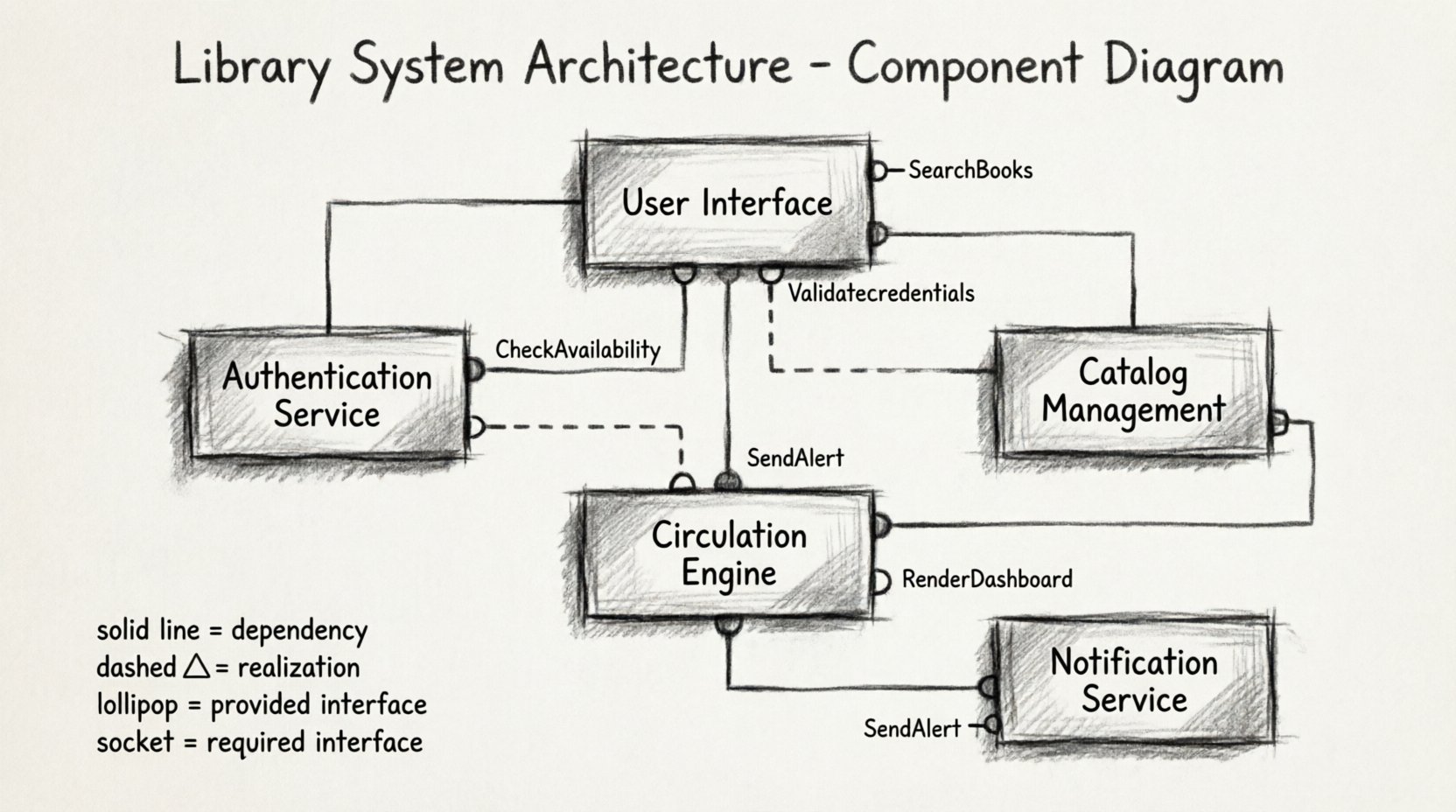
1. User Interface Component
This component acts as the entry point for all interactions. It does not contain business logic but serves as a gateway to the backend services.
- Provides the display for search results.
- Handles input validation for login forms.
- Communicates with the Authentication Service.
2. Authentication Service
Responsible for verifying user credentials and managing session states. This component ensures security across all other modules.
- Validates usernames and passwords.
- Issues secure tokens for active sessions.
- Stores credential hashes in the database.
3. Catalog Management Component
This is the central repository for book metadata. It handles the CRUD (Create, Read, Update, Delete) operations for items.
- Manages ISBNs, titles, and authors.
- Tracks item availability status.
- Supports complex search queries.
4. Circulation Engine
The core logic for lending items. It interacts with the Catalog to check availability and the User Service to verify eligibility.
- Records the transaction date and due date.
- Updates item status to “Checked Out”.
- Triggers fine calculation logic upon return.
5. Notification Service
Handles external communication. It connects to email servers or SMS gateways to inform users about system events.
- Sends overdue reminders.
- Notifies when reserved books are available.
- Alerts staff of system anomalies.
🔌 Defining Interfaces and Ports
Interfaces are the contracts that allow components to communicate. In a component diagram, these are represented as lollipop symbols (provided interfaces) and semi-circles (required interfaces). Understanding these contracts is vital for system integration.
Provided Interfaces
These are services the component offers to others. For example, the Catalog Management Component provides a SearchBooks interface.
SearchBooks(query): Returns a list of matching items.GetBookDetails(id): Returns metadata for a specific item.UpdateStatus(id, status): Changes the availability state.
Required Interfaces
These are services the component needs from others to function. The Circulation Engine requires a CheckAvailability interface from the Catalog.
CheckAvailability(id): Returns true if the item is not borrowed.ValidateMember(id): Returns true if the user has no outstanding fines.
📊 Component Inventory Table
To maintain clarity, we maintain a registry of all components and their primary responsibilities. This table serves as a reference during the modeling process.
| Component Name | Primary Responsibility | Key Provided Interface | Key Required Interface |
|---|---|---|---|
| User Interface | Display and Input Handling | RenderDashboard |
Login, Search |
| Authentication Service | Identity Verification | ValidateCredentials |
DatabaseConnection |
| Catalog Management | Item Metadata Storage | SearchBooks |
DatabaseConnection |
| Circulation Engine | Loan Processing | ProcessReturn |
SearchBooks, ValidateMember |
| Notification Service | External Communication | SendAlert |
UserContactInfo |
🔗 Establishing Relationships
Relationships define how components interact. In UML, we primarily use Dependency and Association relationships for component diagrams.
Dependency
A dependency indicates that one component relies on another to function correctly. If the Authentication Service changes, the User Interface must adapt. This is a standard dependency relationship.
- Direction: From the client (User Interface) to the supplier (Authentication Service).
- Impact: High. Changes in the supplier can break the client.
Realization
This relationship is used when a component implements an interface defined by another component. For instance, a specific implementation of the Catalog Management Component realizes the SearchBooks interface.
- Symbol: A dashed line with a hollow triangle arrow.
- Usage: Often used to show that a concrete component fulfills an abstract contract.
Association
Used for structural relationships where one component holds a reference to another. While less common in high-level architecture, it may represent a direct integration.
🖥️ Detailed Case Study Walkthrough
Let us walk through the construction of the diagram step-by-step, ensuring we capture the logic of the library system.
Step 1: Draw the Component Boxes
Begin by placing the five main components identified earlier on the canvas. Arrange them logically. Place the User Interface at the top, the Services in the middle, and the Database components at the bottom.
Step 2: Define the Ports
For each component, draw small squares or circles on the perimeter to represent ports. Label them clearly. For example, the Circulation Engine needs a port to connect to the Catalog.
- Input Ports: Where data enters the component.
- Output Ports: Where results leave the component.
Step 3: Connect Interfaces
Draw lines connecting the provided interface of one component to the required interface of another. Use the lollipop notation for the provider and the socket notation for the consumer.
For example:
- Connect the
SearchBookslollipop on Catalog Management to theSearchBookssocket on Circulation Engine. - Connect the
Loginsocket on User Interface to theValidateCredentialslollipop on Authentication Service.
Step 4: Add Annotations
Use notes to clarify complex behaviors. For instance, annotate the Circulation Engine with a note explaining the logic for handling reserved items. This adds context that the visual lines alone cannot convey.
📋 Interface Contract Table
Contracts define the signature of operations. Keeping these standardized prevents integration errors later in development.
| Interface Name | Provider Component | Consumer Component | Operation Signature |
|---|---|---|---|
| SearchBooks | Catalog Management | Circulation Engine | Search(query: string): List |
| ValidateMember | Authentication Service | Circulation Engine | CheckEligibility(id: int): boolean |
| SendAlert | Notification Service | Circulation Engine | Notify(message: string): void |
| RenderDashboard | User Interface | None (External) | Display(data: object): void |
🔄 Component Diagram vs. Other Diagrams
It is important to distinguish when to use a component diagram versus other UML artifacts. Using the wrong diagram can lead to confusion among stakeholders.
| Diagram Type | Focus | Best Use Case for Library System |
|---|---|---|
| Class Diagram | Data structures and methods | Designing the Book or User class hierarchy. |
| Sequence Diagram | Temporal flow of messages | Mapping the exact steps of a book loan transaction. |
| Component Diagram | System architecture and modules | Defining the separation of the Search Engine from the Database. |
| Deployment Diagram | Hardware topology | Showing how the application runs on a server cluster. |
When discussing the architecture with project managers or stakeholders, the component diagram is often the most effective tool. It abstracts away the code details while preserving the structural integrity of the system.
🛠️ Best Practices for Modeling
To ensure the diagram remains useful throughout the project lifecycle, adhere to these guidelines.
- Keep it High-Level: Do not include every single method. Focus on major functional groups.
- Use Consistent Naming: Ensure interface names match across components to avoid ambiguity.
- Group Related Components: Use packages or subnets to group components by domain, such as “Admin Module” or “Public Module”.
- Document Assumptions: If a component relies on an external system not shown in the diagram, note this dependency clearly.
- Iterate: The diagram should evolve as requirements change. A static diagram becomes obsolete quickly.
⚠️ Common Pitfalls to Avoid
Even experienced architects make mistakes. Being aware of these common errors can save significant time during development.
1. Over-Engineering Interfaces
Creating too many granular interfaces increases complexity. If two components talk frequently, a single robust interface is often better than multiple small ones.
2. Ignoring Data Flow
A component diagram shows structure, not data flow. Do not assume that connecting two components means data is automatically synchronized. Explicitly model the data transfer mechanisms if necessary.
3. Mixing Concerns
Do not put database access logic inside a user interface component. Keep the UI focused on presentation and the services focused on logic.
4. Circular Dependencies
Avoid situations where Component A depends on Component B, and Component B depends on Component A. This creates a tight coupling that makes refactoring difficult. Use an intermediary interface or event bus to decouple them.
📈 Scaling the Architecture
As the library grows, the system will need to scale. The component diagram provides a framework for this expansion.
- Microservices: Components can eventually be split into independent microservices. The diagram serves as the blueprint for this transition.
- Load Balancing: If the Catalog Management component becomes a bottleneck, the diagram helps identify where to add replicas.
- Third-Party Integration: If a new payment gateway is added, it appears as a new external component connected to the Notification Service.
🔧 Implementation Considerations
While the diagram is a design artifact, it directly influences implementation decisions. Developers will use this model to set up project structures.
- Module Structure: Each component often maps to a specific directory or module in the codebase.
- API Definitions: The interfaces defined in the diagram become the API specifications (e.g., Swagger/OpenAPI documents).
- Testing Strategy: Component testing focuses on the interactions between these units, verifying that the provided interfaces are correctly implemented.
🎯 Final Thoughts on System Design
Modeling a library system with component diagrams provides a robust foundation for development. It clarifies responsibilities, defines contracts, and highlights dependencies before a single line of code is written. By adhering to the principles of modularity and clear interface definition, the system becomes easier to maintain, test, and scale over time.
Remember that diagrams are living documents. As the library system evolves to meet new user needs, update the model to reflect the current state of the architecture. This practice ensures that the documentation remains accurate and valuable to the entire development team.

