The Unified Modeling Language (UML) has long served as the lingua franca of software architecture. For over two decades, the class diagram has stood as a cornerstone for representing the static structure of object-oriented systems. However, the landscape of software engineering is shifting beneath our feet. Cloud-native computing, artificial intelligence, and distributed systems are reshaping how we design, document, and maintain software. This article examines the trajectory of UML class diagrams in this evolving environment, exploring how they adapt to modern constraints and opportunities.
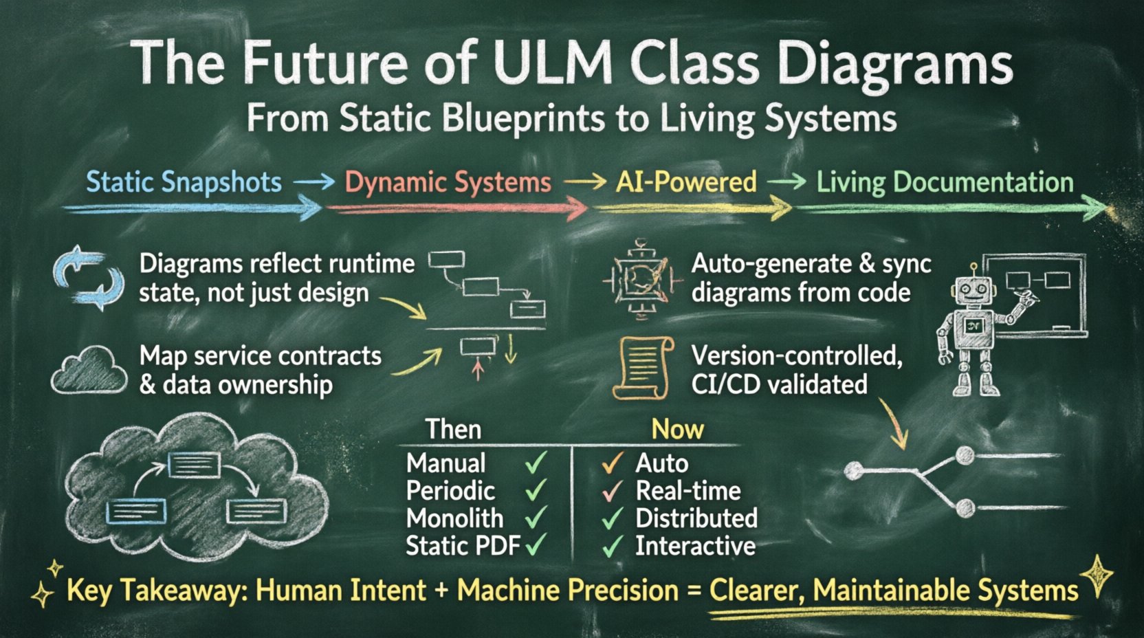
🔄 From Static Snapshots to Dynamic Systems
Traditional UML class diagrams were designed as static blueprints. They depicted classes, attributes, methods, and relationships at a specific point in time. In the era of monolithic applications, this approach provided sufficient clarity. Architects could draw the diagram, developers could implement the code, and the system would follow the plan. Today, systems are dynamic. Services scale, data flows change, and dependencies shift at runtime.
Runtime Relevance: Static diagrams often become obsolete before deployment. The future lies in diagrams that reflect the actual state of the system, not just the design intent.
Dynamic Context: Modern modeling tools are beginning to integrate with runtime telemetry. This allows diagrams to visualize active connections, data flow, and performance bottlenecks.
Behavioral Integration: Pure class diagrams are increasingly supplemented with sequence and state diagrams that capture the interaction flows essential for distributed systems.
This shift does not mean the class diagram is dying. Instead, it is evolving from a standalone artifact into a component of a broader observability and modeling ecosystem. The focus moves from “what does the code look like?” to “how does the system behave?”
🤖 AI and Automated Diagram Generation
One of the most significant challenges with UML class diagrams has been maintenance. As code changes, diagrams often lag behind. Developers forget to update the visual representation, leading to documentation drift. Artificial Intelligence offers a pathway to resolve this friction.
Machine learning models trained on vast codebases can now parse source code and generate structural representations automatically. This process, known as reverse engineering, can create accurate class diagrams from existing repositories. The implications for the future are profound:
Automated Synchronization: Diagrams will update automatically when code commits occur. There will be no need for manual redrawing after every refactor.
Context Awareness: Advanced algorithms can understand the semantic intent of a class, not just its syntax. This allows for better grouping and relationship suggestions.
Code Generation: The flow is bidirectional. Developers can sketch a class structure, and AI can scaffold the boilerplate code, interfaces, and data types required to implement it.
This automation reduces the cognitive load on architects. They spend less time drawing boxes and arrows and more time analyzing system complexity and identifying design flaws.
☁️ Microservices and Distributed Architecture
The migration from monolithic architectures to microservices has introduced a new complexity for class diagrams. In a monolith, classes reside within a single repository. In a distributed system, classes are encapsulated within services, communicating over networks. The traditional class diagram struggles to represent these boundaries clearly.
The future of class diagrams in this context involves redefining the scope of the “class.” It is no longer just about a single file or module. It is about the contract between services.
Service Boundaries: Class diagrams will increasingly serve to map service interfaces. The “class” might represent an API endpoint or a data schema rather than a single code object.
Event-Driven Modeling: Asynchronous communication is standard. Diagrams will need to show event producers and consumers alongside traditional method calls.
Data Ownership: Understanding which service owns which data entity is critical. Future diagrams will emphasize data lineage and ownership to prevent distributed anti-patterns.
This adaptation ensures that the diagram remains a useful tool for understanding the system topology, even when the physical implementation spans multiple servers and containers.
📜 Living Documentation and Version Control
Documentation has historically been a secondary task in software development. It is often written once and forgotten. The future demands that documentation be treated as code. This philosophy, often called “Documentation as Code,” applies directly to UML class diagrams.
By storing diagram definitions in version control systems like Git, teams can leverage the same workflows used for application code. Pull requests can review diagram changes. CI/CD pipelines can validate that diagrams match the source code. This approach ensures that the visual representation is never out of sync with the implementation.
Version History: Teams can track how the architecture evolved over time. This is invaluable for auditing and understanding technical debt.
Collaboration: Multiple architects can work on the model simultaneously, with merge conflict resolution mechanisms handling discrepancies.
Integration: Diagrams become part of the build process. If the code does not match the model, the build can fail, enforcing architectural governance.
This rigor transforms the class diagram from a passive illustration into an active governance tool.
🤝 Collaboration and Communication
Despite technological advancements, the core purpose of a class diagram remains communication. It provides a shared mental model for developers, stakeholders, and product owners. As teams become more distributed and cross-functional, the need for clear visual abstraction increases.
Future diagrams will prioritize clarity over technical completeness. Instead of showing every attribute and method, they will highlight critical relationships and domain concepts. This aligns with Domain-Driven Design (DDD) principles, where the model reflects business logic rather than just technical implementation.
Onboarding: New team members can grasp the system structure faster with accurate, up-to-date diagrams.
Stakeholder Alignment: Business stakeholders often find code difficult to read. A well-structured class diagram bridges the gap between technical reality and business requirements.
Complexity Reduction: As systems grow, diagrams help identify unnecessary complexity, encouraging teams to simplify interfaces and reduce coupling.
📊 Comparison: Traditional vs. Future Modeling Approaches
To understand the shift, it is helpful to compare the characteristics of traditional modeling with emerging trends.
Feature | Traditional Approach | Future Outlook |
|---|---|---|
Creation Method | Manual drawing by architects | AI-assisted generation from code |
Update Frequency | Periodic, often manual | Real-time, automated via CI/CD |
Scope | Monolithic, single repository | Distributed, service-oriented |
Primary Goal | Specification and design | Observability and governance |
Format | Static images or PDFs | Living code, interactive views |
🛠️ Challenges and Limitations
While the trajectory is promising, several challenges remain. The adoption of automated modeling requires a cultural shift within engineering organizations. It demands discipline and investment in tooling. Furthermore, there is a risk of over-modeling. If the system becomes too focused on the diagram, it may lose agility.
Tooling Fragmentation: There is no single standard for “living diagrams.” Teams must choose formats and tools that fit their stack.
Learning Curve: Developers need to understand how to interpret automated diagrams and trust the generation process.
Abstraction Leaks: Diagrams are abstractions. They cannot capture every nuance of runtime behavior. Relying on them too heavily can lead to blind spots.
Addressing these challenges requires a balanced approach. Models should guide development, not dictate it. They are a tool for thinking, not a substitute for engineering.
🔮 The Road Ahead
The evolution of UML class diagrams is a reflection of the maturation of software engineering itself. We are moving from manual craftsmanship to automated precision. The diagram is no longer just a picture of the code; it is a living artifact that interacts with the development lifecycle.
Key trends to watch include deeper integration with observability platforms, more sophisticated AI capabilities for semantic understanding, and tighter coupling with infrastructure-as-code workflows. As these technologies mature, the class diagram will remain relevant, but its form and function will continue to change.
For engineering leaders, the opportunity lies in embracing these changes. By treating diagrams as first-class citizens in the development process, teams can improve code quality, reduce technical debt, and foster better communication. The future of modeling is not about drawing more boxes; it is about creating clearer, more dynamic, and more accurate representations of complex systems.
🛑 Final Thoughts on Architecture
The enduring value of the class diagram lies in its ability to simplify complexity. No matter how advanced the tools become, the human need to visualize relationships and structure remains constant. The future outlook suggests a harmonious blend of human insight and machine efficiency. Architects will define the intent, and tools will handle the representation. This partnership will define the next generation of software design.
As we move forward, the focus should remain on the quality of the design rather than the medium of its representation. Whether drawn by hand or generated by AI, the goal is the same: a robust, maintainable, and understandable system. The class diagram will continue to be a vital instrument in achieving this goal, adapting to the needs of the modern engineer.

