In the landscape of software architecture, few debates stir as much confusion as the relationship between component diagrams and class diagrams. Many teams face a pivotal moment during system design where they must decide: which model serves the project best? Some argue that component diagrams are the future of high-level design, rendering class diagrams obsolete for most contexts. Others insist that without the precision of class structures, components lack a solid foundation.
The reality is far more nuanced. Both diagram types serve critical, distinct functions within the Unified Modeling Language (UML) ecosystem. Understanding when to use one, the other, or both is essential for effective documentation and communication. This guide breaks down the technical distinctions, the appropriate use cases, and the architectural implications of each approach. 🧐
Understanding the Core Purpose of Each Diagram 🔍
To determine if one replaces the other, we must first define what each diagram actually represents. They are not merely different drawings; they are different lenses through which we view the system.
The Class Diagram: The Blueprint of Logic 🧱
A class diagram details the static structure of a system. It focuses on the granular building blocks of software. When a developer opens a class diagram, they expect to see:
- Classes: The fundamental units of code containing data and behavior.
- Attributes: The properties or variables stored within a class.
- Operations: The methods or functions a class can perform.
- Relationships: How classes interact, including inheritance, aggregation, composition, and association.
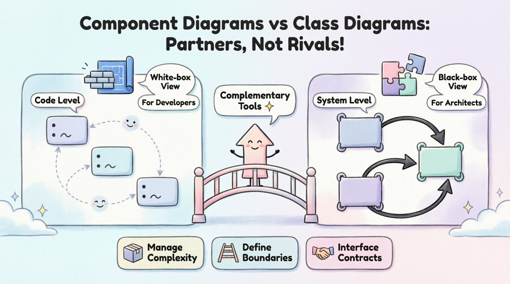
This diagram is the domain of developers and engineers. It answers the question: How is the code organized internally? It is a white-box view, exposing the internal mechanics of the software. If you need to know how data flows between variables or how a specific logic branch is implemented, the class diagram is the source of truth.
The Component Diagram: The Blueprint of Assembly 🧩
A component diagram, in contrast, focuses on the system at a higher level of abstraction. It treats software modules as black boxes. A component represents a modular, deployable unit that encapsulates functionality. Key elements include:
- Components: Physical or logical modules that can be deployed independently.
- Interfaces: The contract a component exposes to other components (provided or required interfaces).
- Dependencies: How components rely on one another to function.
- Ports: Specific points of interaction for incoming or outgoing connections.
This diagram is the domain of architects and system integrators. It answers the question: How do the subsystems fit together? It is a black-box view, hiding internal implementation details to focus on connectivity and structure. If you need to know which services talk to which services or how to deploy a module to a server, the component diagram is the guide.
Key Differences at a Glance 📊
While both diagrams describe structure, they operate at different abstraction levels. The table below outlines the technical distinctions that prevent one from simply replacing the other.
| Feature | Class Diagram | Component Diagram |
|---|---|---|
| Abstraction Level | Granular (Code level) | Coarse-grained (System level) |
| Primary Audience | Developers, Implementers | Architects, Integrators |
| View Type | White-box (Internal logic) | Black-box (External interface) |
| Focus | Attributes, Methods, Logic | Interfaces, Ports, Connections |
| Deployment Context | Abstract (Logic only) | Physical/Logical (Deployable units) |
| Stability | Changes frequently with code | Changes less frequently |
Notice that the stability factor is significant. Class diagrams evolve as the code is refactored daily. Component diagrams often remain stable for months or years, serving as a contract for the system architecture. This difference in lifecycle suggests they are complementary rather than interchangeable.
The Abstraction Gap: Why Both Are Necessary 📉
Software systems are too complex to be represented by a single view. This is the concept of the Abstraction Gap. If you try to model a massive enterprise system using only class diagrams, the resulting model becomes unreadable. It is akin to looking at a city map where every brick in every building is drawn. You lose the ability to see the roads and districts.
Conversely, if you model the entire system using only component diagrams, you lose the ability to debug specific logic errors. You know which service is failing, but not which function within that service is causing the crash.
1. Managing Complexity
Component diagrams help manage complexity by grouping classes into cohesive modules. This allows teams to work in parallel without stepping on each other’s toes. Team A can own the Authentication Component, while Team B owns the Reporting Component. They agree on the interfaces between them. The internal class structures of Team A do not concern Team B, provided the interface remains unchanged.
2. Defining Boundaries
Component diagrams explicitly define system boundaries. They clarify where one subsystem ends and another begins. This is crucial for microservices architecture, where services are deployed independently. A class diagram cannot easily convey deployment boundaries or physical separation.
3. Interface Contracts
The primary role of a component diagram is to define contracts. It specifies what a component requires and what it provides. This decoupling allows for implementation changes. You can rewrite the internal logic of a component (changing class structures) without affecting the rest of the system, as long as the component diagram interfaces remain valid.
When to Use Class Diagrams 🧑💻
There are specific scenarios where the class diagram is the superior tool, and no amount of component modeling can substitute it.
- Database Schema Design: When mapping objects to relational tables, the relationships between classes (foreign keys, one-to-many associations) are critical.
- Complex Algorithms: If a feature relies on intricate state management or specific inheritance hierarchies, a class diagram clarifies the flow.
- Refactoring Planning: Before moving code from one class to another, understanding the current dependencies is vital to avoid breaking functionality.
- Onboarding New Developers: New hires need to understand the data structures and logic flow to contribute effectively. Component diagrams are too high-level for this task.
In these cases, the component diagram acts as a map of the country, while the class diagram is the street-level navigation. You need both to reach your destination.
When to Use Component Diagrams 🏗️
Component diagrams shine when the focus shifts from implementation to integration and architecture.
- System Integration: When combining legacy systems with new modules, you need to show how data flows between them without detailing the legacy code.
- Deployment Planning: Identifying which modules go on which servers or containers requires a component view.
- Security Audits: Defining trust boundaries between components is easier when the internal code is hidden behind interface contracts.
- High-Level Stakeholder Communication: Project managers and non-technical stakeholders need to understand the system flow without getting bogged down in variable names or method signatures.
Here, the class diagram is the engine room, while the component diagram is the ship’s bridge. The captain needs the bridge view to navigate, even if the engineers need the engine room view to maintain.
The Evolution of Abstraction: Refining the Model 🔄
One common misconception is that you choose one diagram type and stick with it. In reality, software design is iterative. A component diagram often serves as the starting point for a new project. As the project matures, the internal logic of each component is fleshed out using class diagrams.
Top-Down Design
In this approach, you start with the component diagram to define the architecture. Once the architecture is approved, teams break down each component into class diagrams. This ensures that the implementation aligns with the architectural intent. If a class structure emerges that does not fit the component boundaries, the architecture is revisited.
Bottom-Up Design
Alternatively, teams might start with class diagrams for a specific module. Once the module is stable, it is wrapped into a component definition. This is common in legacy modernization efforts where existing code is refactored into new components.
Regardless of the direction, the two models must remain synchronized. A change in the class diagram that alters an interface must be reflected in the component diagram. A change in the component diagram that removes a dependency must be checked against the class diagrams to ensure no orphaned code remains.
Common Modeling Pitfalls ⚠️
Even with clear definitions, teams often make mistakes that blur the lines between these diagrams. Recognizing these pitfalls helps maintain clarity.
1. Over-Engineering Components
Creating too many small components leads to a fragmented system. If every class is a component, you lose the benefit of abstraction. A component should represent a meaningful unit of deployment or logic, not a single file or class.
2. Ignoring Internal Dependencies
Some teams model components without considering the internal class dependencies that might violate the component’s boundary. For example, if Component A calls a private method inside Component B, the component diagram is lying. This tight coupling should be visible in the class diagram, but the component diagram must show the correct interface usage.
3. Mixing Concerns
A common error is putting class-level details inside a component diagram. Avoid showing method signatures inside a component box unless they are part of the public interface. Keep the component diagram clean. If you need to see the method signatures, look at the class diagram.
4. Neglecting Interfaces
Component diagrams are useless without clear interfaces. If a component box is just a blob with no provided or required ports, it provides no value. Always define the contract. This makes the diagram actionable for developers.
Integrating Both in Your Workflow 🛠️
To get the best of both worlds, integrate these diagrams into your documentation workflow. They should not be static artifacts created once and forgotten. They are living documents that evolve with the code.
- Design Phase: Start with component diagrams to agree on the high-level structure. Use class diagrams to validate complex logic.
- Development Phase: Focus on class diagrams for implementation. Update component diagrams only when architecture changes.
Review Phase: Use component diagrams for architectural reviews. Use class diagrams for code quality reviews.- Maintenance Phase: Update class diagrams when refactoring. Update component diagrams when adding new modules.
This workflow ensures that the architecture remains stable while the implementation remains flexible. It prevents the common scenario where the documentation diverges from the code.
The Role of Abstraction in Long-Term Success 🚀
The decision to use both diagrams is not just about documentation; it is about long-term maintainability. Systems that rely solely on class diagrams often suffer from architectural drift. Developers focus on the immediate logic and ignore the broader structure, leading to spaghetti code.
Systems that rely solely on component diagrams often suffer from integration issues. Teams do not understand the internal constraints of the modules they are connecting, leading to brittle systems.
By maintaining both, you create a system that is both coherent and flexible. The component diagram protects the architecture from change, while the class diagram allows for innovation within the boundaries. This balance is the hallmark of robust engineering.
Final Thoughts on Diagram Selection 📝
The question of whether component diagrams replace class diagrams is answered by examining the needs of the project. If you need to manage complexity, define boundaries, and communicate with stakeholders, the component diagram is essential. If you need to implement logic, debug errors, and manage data structures, the class diagram is essential.
They are not rivals. They are partners in the design process. One looks at the forest, and the other looks at the trees. A healthy ecosystem requires both. By understanding the distinct roles of each diagram, you can avoid the trap of choosing one over the other. Instead, leverage both to create a system that is well-architected and well-implemented.
As you move forward with your next project, consider the layer of abstraction required at each stage. Do not force a square peg into a round hole. Use the right tool for the job. This disciplined approach to modeling will save time, reduce errors, and improve the overall quality of your software. 🛠️

