


Understanding the architecture of a software system is fundamental for any developer or system designer. One of the most powerful tools for visualizing this structure is the component diagram. For students beginning their journey in software engineering, grasping how to model system components is essential for bridging the gap between abstract requirements and concrete implementation.
This guide provides a detailed walkthrough of component diagrams. We will explore the notation, the rules of construction, and the practical steps to create effective diagrams without relying on specific proprietary tools. The focus remains on the core concepts of Unified Modeling Language (UML) and system design principles.
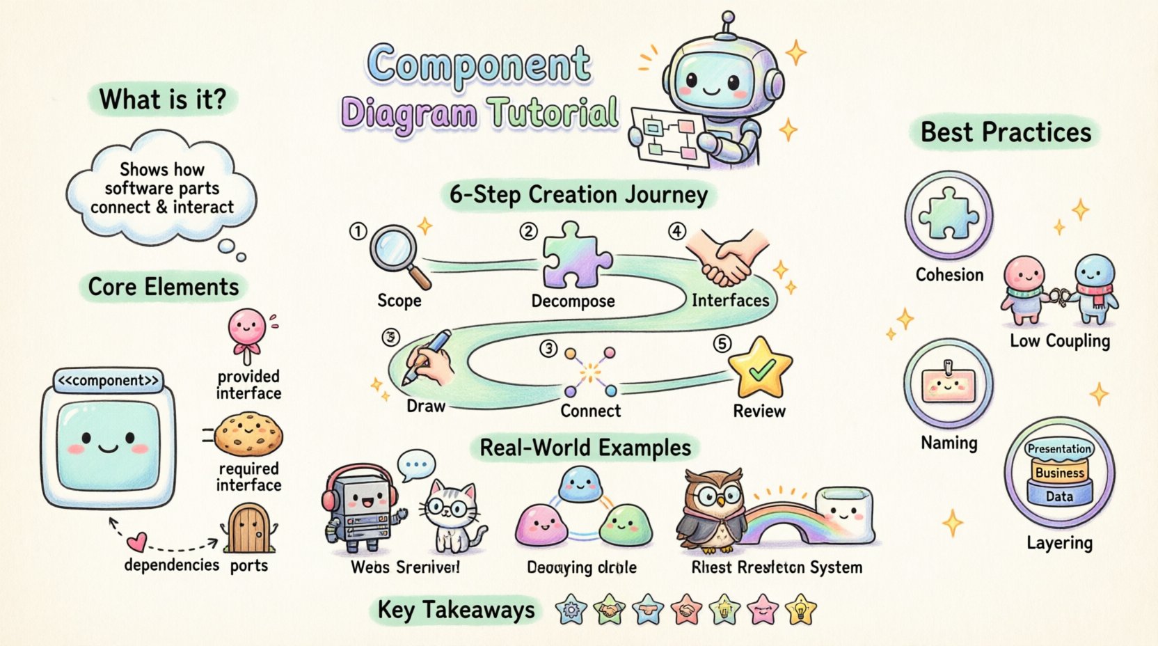
📋 What is a Component Diagram?
A component diagram is a type of static structure diagram in UML. It describes the organization and wiring of the components in a system. Unlike class diagrams, which focus on detailed code structures, component diagrams operate at a higher level of abstraction. They represent the physical or logical building blocks of the system.
Key characteristics include:
- Abstraction: They hide internal implementation details to show external interfaces.
- Modularity: They emphasize the separation of concerns and modular design.
- Deployment Context: They often relate to how components are deployed in a runtime environment.
🧱 Core Elements of a Component Diagram
To draw a component diagram effectively, you must understand the specific symbols used. These symbols convey relationships and functionality without needing text descriptions for every connection.
1. The Component Symbol
The primary symbol is a rectangle with a specific tab on the upper left. This tab indicates the stereotype, usually <<component>>.
- Name: Located inside the rectangle, typically in bold.
- Properties: You can list attributes or methods below the name if detailed information is required.
- Stereotype: The text <<component>> or <<library>> helps classify the type of artifact.
2. Interfaces
Interfaces define the contract of interaction. They are crucial for decoupling components. There are two main types:
- Provided Interface: A “lollipop” shape. It indicates the functionality the component offers to others.
- Required Interface: A “socket” shape (semicircle). It indicates the functionality the component needs from others.
3. Ports
Ports are the points of interaction on a component. While often implicit, explicit ports help clarify where connections occur. They can be labeled to specify the nature of the connection (e.g., “Input”, “Output”, “API Gateway”).
4. Dependencies
Dependencies are represented by dashed lines with open arrowheads. They indicate that one component relies on another to function correctly.
🛠️ Step-by-Step Guide to Creating a Diagram
Creating a robust diagram requires a methodical approach. Follow these steps to ensure your model accurately reflects the system design.
Step 1: Identify the Scope and Context
Before drawing a single line, define the boundaries of the system. Are you modeling the entire enterprise system, or just a specific microservice? Knowing the scope prevents clutter.
- Define the system boundary.
- Identify external systems that interact with the main application.
- Decide on the level of detail required for the audience.
Step 2: Decompose the System
Break down the system into major functional areas. Group related functionalities together.
- Example: Separate the “User Management” module from the “Payment Processing” module.
- Example: Isolate the “Database Access” layer from the “Presentation” layer.
Step 3: Define Interfaces
For each component, determine what it provides and what it requires. This is the most critical step for maintaining low coupling.
- List the API methods exposed by the component.
- List the external services the component consumes.
- Ensure interfaces are abstract; do not expose database schemas or internal variables.
Step 4: Draw the Components
Place the rectangles on your canvas. Arrange them logically.
- Group components by layer (e.g., Frontend, Backend, Data).
- Use color coding sparingly to indicate status or type (e.g., third-party vs. internal), though standard black and white is preferred for technical clarity.
- Ensure names are clear and concise.
Step 5: Connect the Components
Draw lines to show relationships. Use the appropriate arrow types.
- Realization: Solid line with a hollow triangle arrow (Interface implementation).
- Dependency: Dashed line with an open arrow (Usage).
- Association: Solid line (Direct relationship).
Step 6: Review and Refine
Check the diagram for consistency and correctness.
- Are there circular dependencies?
- Do all required interfaces have a provider?
- Is the diagram readable at a glance?
📊 Component vs. Other UML Diagrams
Students often confuse component diagrams with class or sequence diagrams. Understanding the distinction is vital for selecting the right tool for the job.
| Diagram Type | Primary Focus | Level of Abstraction | When to Use |
|---|---|---|---|
| Component Diagram | System structure and modularity | High (Logical/Physical) | Architectural planning, deployment structure |
| Class Diagram | Object-oriented design and data | Medium (Code level) | Developing specific classes, database schema |
| Sequence Diagram | Interaction over time | Medium (Behavioral) | Defining logic flow, API call sequences |
| Deployment Diagram | Hardware and infrastructure | Low (Physical) | Server setup, cloud infrastructure mapping |
🚀 Best Practices for Students
Creating a diagram is one thing; creating a good diagram is another. Adhere to these principles to improve the quality of your work.
1. Maintain High Cohesion
Components should have a single, well-defined purpose. If a component handles both user authentication and payment processing, it is too large. Split it into “Auth Service” and “Billing Service”.
2. Minimize Coupling
Components should depend on abstractions, not concretions. Use interfaces to define connections. If Component A changes its internal logic, Component B should not break as long as the interface remains the same.
3. Consistent Naming Conventions
Use clear, descriptive names. Avoid abbreviations unless they are industry standard.
- Good: “OrderProcessor”, “InventoryManager”
- Bad: “OP”, “InvMgr”, “Module1”
4. Document Dependencies
If a dependency is complex, add a note or label to the connecting line. Explain why the dependency exists.
5. Layering Strategy
Organize your diagram by architectural layers. Typically, this flows from top to bottom:
- Presentation Layer: User interface components.
- Business Logic Layer: Core processing components.
- Data Access Layer: Database and storage components.
🚧 Common Mistakes to Avoid
Even experienced designers make errors. Students should be aware of these pitfalls to save time during revisions.
- Over-Engineering: Trying to model every single class in a component diagram. Keep it high-level. If a component is a simple class, do not draw it as a component unless it is a deployable unit.
- Crossing Dependencies: Lines crossing each other make the diagram messy. Use “swimlanes” or reposition components to reduce clutter.
- Missing Interfaces: Connecting components directly without an interface creates tight coupling. Always prefer interface-based connections.
- Ignoring Physical Deployment: A component diagram often implies where the code lives. Ensure you distinguish between logical components and physical files or servers if the diagram is for deployment.
- Static Thinking: Remember that components interact at runtime. A static diagram should reflect potential runtime behavior, not just file structures.
💡 Real-World Scenarios
To make the concepts concrete, let us look at how component diagrams apply in different contexts.
Scenario 1: Web Application Architecture
In a typical web app, you might see the following components:
- Web Server: Handles HTTP requests.
- API Gateway: Routes traffic to specific microservices.
- Auth Service: Manages user sessions and tokens.
- Database Service: Handles persistence.
The Web Server requires the Auth Service. The API Gateway provides an interface to the Auth Service. The Database Service provides storage interfaces to both the Gateway and the Auth Service.
Scenario 2: Microservices Ecosystem
Microservices rely heavily on component diagrams to define boundaries. Each service is a component. The diagram shows which services talk to which.
- Service Discovery: A component that helps other components find each other.
- Message Queue: An asynchronous communication component.
- Load Balancer: Distributes traffic across multiple instances.
Here, the component diagram is crucial for understanding the network topology.
Scenario 3: Legacy System Integration
When integrating new software with old systems, a component diagram helps visualize the wrapper or adapter.
- Adapter Component: Translates new API calls into legacy system commands.
- Legacy Component: The old system, often treated as a black box.
This clarifies where the risk of failure lies during the integration process.
📝 Practical Exercises for Students
Learning by doing is the most effective method. Try these exercises to solidify your understanding.
- Draw a Library System: Model the “Book Catalog”, “Member Registration”, and “Loan Processing” components. Define the interfaces for searching books and issuing loans.
- Map a Mobile App: Create a diagram for a weather app. Include “UI Component”, “Network Request Component”, and “Data Parser Component”. Show how they connect.
- Refactor a Class Diagram: Take a complex class diagram and group classes into components. Identify the public interfaces for each group.
- Identify Coupling: Draw a diagram with circular dependencies. Then, refactor it by introducing an interface to break the cycle.
🔧 Tools and Implementation
While the concepts are tool-agnostic, you will need software to create these diagrams. The industry offers various options, ranging from open-source to commercial suites.
When selecting a modeling tool, consider the following:
- UML Compliance: Does it support the standard notation?
- Export Options: Can you export to PDF, PNG, or XML?
- Collaboration: Does it allow multiple users to work on the same diagram?
- Code Generation: Does it support reverse engineering from code?
Regardless of the tool you choose, remember that the diagram is a communication tool. It is meant to be read by humans, not just processed by machines. Simplicity wins over complexity.
🔄 Component Diagram in the SDLC
Where does this fit in the Software Development Life Cycle?
- Requirements Phase: High-level components are identified based on functional requirements.
- Design Phase: Detailed interfaces and dependencies are defined. This is the primary phase for component modeling.
- Implementation Phase: Developers use the diagram to understand where their code fits. They ensure their implementation matches the defined interfaces.
- Testing Phase: Testers use the diagram to understand component boundaries for integration testing.
- Maintenance Phase: When changes occur, the diagram is updated to reflect the new architecture.
📌 Summary of Key Takeaways
- Component diagrams visualize the high-level structure of software systems.
- Interfaces (lollipops and sockets) are critical for decoupling components.
- Follow a systematic process: Scope, Decompose, Define, Draw, Connect, Review.
- Avoid circular dependencies and high coupling to ensure maintainability.
- Use diagrams to communicate architecture to stakeholders, developers, and testers.
- Keep the diagram updated as the system evolves.
By mastering these concepts, you build a foundation for professional software architecture. The ability to visualize system structure is a skill that distinguishes a junior developer from a senior engineer. Practice these techniques regularly, and you will find yourself designing more robust and scalable systems.

