


Unified Modeling Language (UML) serves as the backbone for object-oriented software design. Among the various diagram types available, the Class Diagram stands out as the most critical for visualizing the static structure of a system. Understanding every component within this diagram is essential for developers, architects, and analysts to communicate complex system designs clearly. This guide provides a deep dive into the anatomy of a UML Class Diagram, ensuring you can read and create them with precision.
🔍 The Purpose of Class Diagrams
Class diagrams are structural diagrams that describe the structure of a system by showing the system’s classes, their attributes, operations, and the relationships among objects. Unlike sequence diagrams that capture dynamic behavior over time, class diagrams remain static. They act as a blueprint, much like architectural plans for a building, defining the foundation upon which the code will be built.
Key objectives include:
- Documenting the static view of an object-oriented system.
- Providing a basis for code generation and reverse engineering.
- Facilitating communication between technical and non-technical stakeholders.
- Identifying potential design flaws before implementation begins.
🏗️ The Class Box: Core Structure
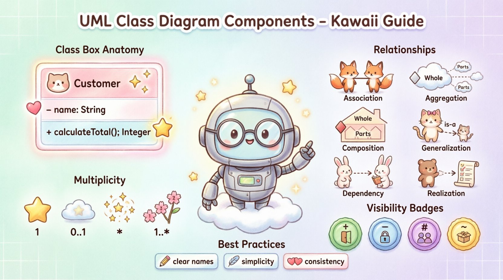
The fundamental building block of a class diagram is the Class Box. It is a rectangular shape divided into compartments. A standard class box typically contains three sections: the class name, attributes, and operations. While not all sections are mandatory, a complete diagram usually displays all three to provide full context.
1. The Name Compartment
The top section of the box holds the name of the class. This name should be a noun or a noun phrase that clearly identifies the entity. Naming conventions are crucial for readability and maintainability.
- Capitalization: Class names typically start with a capital letter (e.g., Customer, Invoice).
- Uniqueness: Names should be unique within the namespace to avoid ambiguity.
- Singular vs. Plural: Use singular nouns for classes (e.g., Product, not Products) to represent the type, not the collection.
2. The Attribute Compartment
The middle section lists the attributes. Attributes represent the state or data held by an instance of the class. They define what information the class knows about itself.
When documenting attributes, consider the following elements:
- Name: Usually in lowercase, often prefixed with a visibility symbol.
- Type: The data type (e.g., String, Integer, Date).
- Default Value: If an attribute has a standard starting value, it can be shown (e.g., status = “active”).
Example: - name: String indicates a private string attribute named name.
3. The Operation Compartment
The bottom section lists operations. Operations represent the behavior or methods available to the class. They define what the class can do.
Key details for operations include:
- Visibility: Symbols indicating access levels (+, -, #, ~).
- Name: Usually in lowercase, starting with a verb (e.g., calculateTotal).
- Parameters: Arguments required to perform the operation.
- Return Type: The data type returned after the operation completes.
Example: + calculateTotal(): Integer indicates a public operation that returns an integer.
🔗 Understanding Relationships
Relationships define how classes interact with one another. They are the lines connecting the class boxes. Misinterpreting these relationships can lead to significant architectural errors in the final codebase. Below is a detailed breakdown of the standard UML relationships.
Relationship Comparison Table
| Relationship Type | Symmetry | Semantic Meaning | Notation |
|---|---|---|---|
| Association | Optional | A structural link between instances | Solid line |
| Aggregation | Weak | A whole-part relationship (part can exist without whole) | Solid line with empty diamond |
| Composition | Strong | A whole-part relationship (part cannot exist without whole) | Solid line with filled diamond |
| Generalization | Yes | An inheritance relationship (is-a) | Solid line with hollow triangle |
| Dependency | No | Usage relationship (one class uses another) | Dashed line with open arrow |
| Realization | No | Implementation of an interface | Dashed line with hollow triangle |
Association
An association represents a structural link between objects. It indicates that objects of one class are connected to objects of another class. This is the most basic relationship.
- It can be named to describe the nature of the link.
- It can be bidirectional or unidirectional.
- It does not imply ownership or lifecycle management.
Aggregation
Aggregation is a specialized form of association. It represents a “has-a” relationship where the part can exist independently of the whole.
- Example: A University has Departments. If the University closes, the Department data might still exist in a legacy system, or departments can be transferred.
- Visualized by an empty diamond at the “whole” end of the line.
Composition
Composition is a stronger form of aggregation. It implies a lifecycle dependency. If the whole is destroyed, the parts are destroyed with it.
- Example: A House has Rooms. If the House is demolished, the Rooms cease to exist.
- Visualized by a filled diamond at the “whole” end of the line.
Generalization (Inheritance)
Generalization represents an “is-a” relationship. It allows one class to inherit attributes and operations from another.
- The child class is a specialized version of the parent class.
- It promotes code reusability.
- Visualized by a solid line with a hollow triangle pointing to the parent class.
Dependency
Dependency indicates that one class uses another. This is often a temporary relationship, such as passing an object as a parameter to a method.
- Changes in the supplier class may affect the dependent class.
- Visualized by a dashed line with an open arrow.
Realization (Interface)
Realization shows that a class implements an interface. The class promises to provide the behavior defined in the interface.
- Visualized by a dashed line with a hollow triangle.
- Often used to achieve polymorphism and decouple implementation from interface.
🔢 Multiplicity and Cardinality
Multiplicity defines how many instances of one class relate to one instance of another class. It is a critical detail for database design and logic validation. Multiplicity is usually placed near the ends of the association lines.
Common Multiplicity Notations
- 1: Exactly one instance.
- 0..1: Zero or one instance (optional).
- 1..*: One or more instances.
- 0..*: Zero or more instances (many).
- *: A shorthand for 0..*.
- 1..5: A specific range of instances.
Scenario: Consider a Student and a Course. A Student must enroll in at least one Course (1..*), but a Course can have zero Students (0..*). This is represented by placing “1..*” next to the Course on the Student side and “0..*” next to the Student on the Course side.
🎨 Visibility Modifiers
Visibility determines which parts of a class are accessible from other classes. This is a fundamental concept in encapsulation. The symbols are placed at the beginning of the attribute or operation name.
- Public (+): Accessible from any other class. This is the most open level of access.
- Private (-): Accessible only within the class itself. This protects internal data.
- Protected (#): Accessible within the class and its subclasses. Common in inheritance hierarchies.
- Package (~): Accessible only within the same package or namespace.
Choosing the correct visibility is vital for maintaining the integrity of the object state. Overuse of public access can lead to tight coupling and fragile code.
📝 Stereotypes and Constraints
Beyond the standard elements, UML allows for extension through stereotypes and constraints. These add semantic meaning without changing the visual structure.
Stereotypes
A stereotype is a mechanism to create new types of elements. It is enclosed in guillemets (e.g., <<stereotype>>).
- Example: <<Interface>> indicates a class that defines an interface.
- Example: <<Entity>> might indicate a database table mapping.
- Example: <<Abstract>> indicates a class that cannot be instantiated directly.
Constraints
Constraints are conditions that must be met by the system. They are enclosed in curly braces (e.g., {constraint}).
- Example: {unique} on an attribute ensures no duplicates.
- Example: {readOnly} on an attribute ensures it cannot be modified.
- Example: {pre: age >= 18} on an operation ensures the logic holds true.
🛠️ Best Practices for Design
Creating a class diagram is not just about drawing boxes and lines; it is about modeling logic correctly. Adhering to best practices ensures the diagram remains useful over time.
Naming Conventions
- Use clear, descriptive names.
- Avoid abbreviations unless they are industry standard.
- Ensure consistency across the entire diagram.
Simplicity
- Avoid showing every single attribute in a diagram. Focus on the essential ones.
- Do not clutter the diagram with operations that are trivial.
- Use inheritance wisely. Deep hierarchies can become difficult to manage.
Consistency
- Ensure relationships are consistent. If A is associated with B, the direction should be clear.
- Maintain the same style for visibility symbols throughout.
- Keep multiplicity consistent with business rules.
⚠️ Common Pitfalls to Avoid
Even experienced modelers can make mistakes. Being aware of common errors helps in producing cleaner diagrams.
- Circular Dependencies: Avoid loops where Class A depends on Class B, which depends on Class A. This creates compilation issues in many languages.
- Confusing Aggregation and Composition: These are often mixed up. Remember: Composition implies ownership and lifecycle.
- Over-Engineering: Do not model every detail of the system in one diagram. Split large systems into subsystems.
- Ignoring Visibility: Showing only private attributes can hide important data structures, while showing only public ones can expose security risks.
- Misusing Generalization: Not every “has-a” relationship is inheritance. Inheritance is strictly “is-a”.
📈 Application in Development Lifecycle
Class diagrams are not static documents; they evolve with the project.
Analysis Phase
During the analysis phase, class diagrams focus on business concepts. They do not need to be technically perfect but should accurately reflect domain logic.
Design Phase
In the design phase, technical details are added. Visibility, data types, and specific relationships are defined. This is the version that developers use to write code.
Maintenance Phase
As changes occur, the diagram must be updated. An outdated diagram is worse than no diagram, as it misleads developers and causes technical debt.
🧩 Advanced Considerations
For complex systems, standard class diagrams may need extensions.
- Interfaces: Using interfaces allows for loose coupling. Classes implement interfaces, allowing the implementation to change without affecting the client.
- Abstract Classes: These define a common interface but cannot be instantiated. They are useful for grouping common behavior.
- Associative Classes: When an association itself has attributes or operations, it can be modeled as an associative class. This is common in many-to-many relationships.
📌 Summary of Key Takeaways
Mastering the components of a UML Class Diagram requires attention to detail and a solid understanding of object-oriented principles. From the basic class box to complex relationships like composition and generalization, each element plays a specific role in defining system architecture.
- Class Boxes: Define structure with name, attributes, and operations.
- Relationships: Define interactions via association, aggregation, composition, inheritance, dependency, and realization.
- Multiplicity: Define cardinality and constraints on relationships.
- Visibility: Control access to data and behavior.
- Best Practices: Prioritize clarity, consistency, and accuracy.
By utilizing these elements correctly, teams can build robust, maintainable, and scalable software systems. The diagram serves as a shared language, bridging the gap between abstract requirements and concrete implementation.

