


Software architecture relies heavily on visual communication. When teams design systems, they need a shared language to describe structure. The class diagram stands as one of the most critical artifacts in this process. It defines the blueprint of the system. However, not all blueprints look the same. Different standards and syntaxes exist to represent these structures. This guide explores how various notations handle the representation of classes. We will examine the nuances of attributes, operations, and relationships across different modeling conventions.
Understanding Class Diagram Fundamentals 🏗️
A class diagram describes the static structure of a system. It identifies classes, their attributes, operations, and the relationships among objects. In object-oriented design, this diagram serves as the backbone for implementation. Developers use these diagrams to understand how data flows and how behavior is encapsulated. The core unit is the class box. This box is divided into compartments. Typically, there are three distinct areas within this box.
- Class Name: The top compartment identifies the entity.
- Attributes: The middle compartment lists data members.
- Operations: The bottom compartment defines methods or functions.
While the concept remains consistent, the visual syntax changes. Some standards use specific symbols for visibility. Others rely on textual prefixes. Understanding these differences is vital for interoperability between tools and teams.
Core Elements of Class Notation 📐
The class box itself is the primary focus of comparison. How information is conveyed within this box determines readability and precision. Let us break down the specific elements that define a class in a diagram.
Attributes and Visibility 🔒
Attributes represent the state of a class. In a diagram, they are listed as properties. The most significant variation occurs in how visibility is denoted. This indicates who can access the data. The standard convention uses symbols placed before the attribute name.
- Public (+): Accessible by any other class.
- Private (-): Accessible only by the class itself.
- Protected (#): Accessible by the class and its subclasses.
- Package (~): Accessible within the same package or namespace.
Different notation systems handle these symbols differently. Some graphical tools require explicit selection of icons. Text-based syntaxes often require typing the symbol directly. The absence of a symbol usually implies a default state, but this default varies by standard. Some conventions assume private by default, while others assume public. This ambiguity can lead to confusion in cross-team collaboration.
Operations and Methods ⚙️
Operations define the behavior of a class. They are the actions an object can perform. Like attributes, visibility applies here as well. The syntax for operations often includes return types. This is crucial for understanding data flow.
- Name: The identifier of the method.
- Parameters: Input data required to run the method.
- Return Type: The data output produced by the method.
Notation variance is high in this section. Some styles list parameters in parentheses immediately following the name. Others place them on a separate line. In some text-based notations, the return type is appended to the name with a colon. In others, it appears in a dedicated column. Consistency in listing these details ensures that the diagram remains a reliable specification.
Relationship Representations 🔗
Classes rarely exist in isolation. They connect to other classes through relationships. These lines define the structural links. The notation used for these lines carries semantic meaning. Misinterpreting a line type can lead to architectural errors.
Association vs. Dependency
An association represents a structural link. It implies that one class holds a reference to another. A dependency implies a usage relationship. It suggests that one class needs another to function but does not hold its state.
- Association: Typically a solid line. It may include multiplicity numbers like 1, 0..1, or *.
- Dependency: Often a dashed line with an open arrow head.
Some notations merge these concepts. In certain simplified diagrams, all lines are solid. The context determines the meaning. In strict standards, the line style is mandatory. This distinction helps developers understand the lifecycle of the connected objects.
Inheritance and Composition
Inheritance shows a hierarchy. A subclass inherits from a superclass. This is usually depicted with a solid line and a hollow triangle arrowhead. Composition is a stronger form of association. It implies ownership. If the parent object is destroyed, the child object ceases to exist.
- Generalization: Solid line, hollow triangle.
- Composition: Solid line, filled diamond at the parent end.
- Aggregation: Solid line, hollow diamond at the parent end.
Different platforms render these shapes with slight variations. The angle of the triangle or the size of the diamond may differ. While visually distinct, the semantic intent must remain identical. If a notation changes the shape without changing the meaning, it is a stylistic choice. If it changes the meaning, it is a syntax conflict.
Variations Across Modeling Standards 📊
Several major standards exist for modeling systems. While they share a common goal, their syntax rules differ. Comparing these helps teams choose the right approach for their workflow.
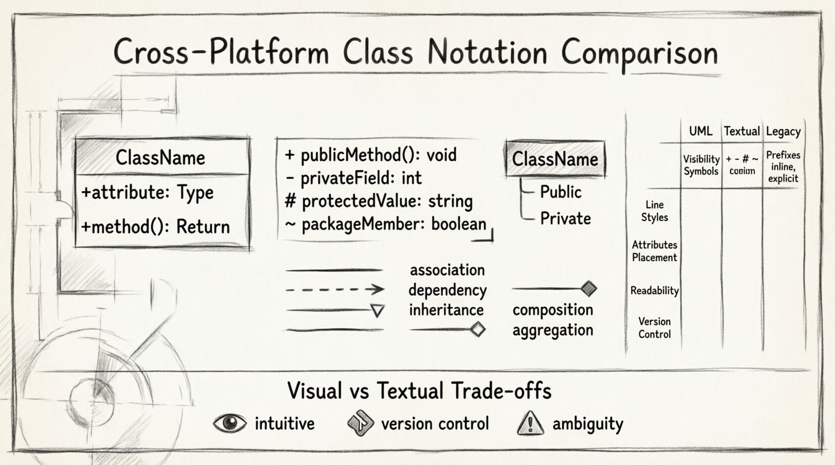
| Feature | Standard UML 2.x | Textual Syntax | Legacy Notations |
|---|---|---|---|
| Visibility Symbol | +, -, # |
+, -, # (often explicit) |
Text labels (Public, Private) |
| Line Style | Solid, Dashed, Open Arrow, Filled Diamond | ASCII characters (-, –>, *–) | Simple lines with labels |
| Attributes | Compartment in box | List in code block | Side tables |
| Readability | High (Visual) | Medium (Requires parsing) | Low (Ambiguous) |
| Version Control | Difficult (Binary/Graph) | Easy (Text-based) | Moderate |
This table highlights the trade-offs. Visual standards offer immediate clarity. Textual syntaxes offer easier version control. Legacy notations often prioritize simplicity over precision. Teams must weigh these factors when selecting a modeling approach.
Textual vs. Visual Syntax 📝
The medium of representation affects how classes are defined. Visual diagrams are intuitive. They allow architects to see the system at a glance. Text-based syntaxes are precise. They can be stored in code repositories and processed by scripts.
Visual Diagrams
- Pros: Intuitive for stakeholders, immediate feedback on structure.
- Cons: Hard to version control, prone to manual errors, file formats can be proprietary.
Visual tools often store diagrams in proprietary formats. This can lock teams into specific ecosystems. When moving between platforms, data loss can occur. Converting a visual diagram to text often requires reformatting. This process introduces friction into the development lifecycle.
Text-Based Syntaxes
- Pros: Version control friendly, easy to automate, portable across platforms.
- Cons: Steeper learning curve, requires mental translation to visual form.
Text-based definitions allow the diagram to live alongside the source code. This keeps the documentation synchronized with the implementation. If a class changes in code, the text definition can be updated in the same commit. This reduces the risk of documentation drift. However, the readability suffers for non-technical stakeholders. A visual summary is often needed for presentations.
Maintaining Consistency in Large Systems 🌐
As systems grow, the number of classes increases. Managing this complexity requires strict adherence to notation rules. Inconsistency creates noise. It forces readers to decode meaning on the fly.
Standardization Rules
- Visibility: Always use symbols. Do not mix symbols and words.
- Spacing: Maintain consistent indentation for nested attributes.
- Names: Use camelCase for attributes, PascalCase for classes.
- Relationships: Label every association with its role.
Without these rules, a diagram becomes a puzzle. Developers spend time deciphering symbols rather than understanding logic. Automated linting tools can help enforce these rules. They check for missing visibility symbols or incorrect line types. This ensures that the output remains consistent regardless of who creates the diagram.
Common Pitfalls in Notation 🚫
Even with standards, errors occur. These mistakes often stem from ambiguity or tool limitations. Recognizing them helps teams avoid structural flaws.
- Mixing Notations: Using UML 1.x symbols in a UML 2.x diagram creates confusion. The multiplicity rules changed between versions.
- Missing Multiplicity: Failing to specify how many objects participate in a relationship. Is it one or many? This affects database schema design.
- Abstract Classes: Forgetting to italicize the name of an abstract class. This hides important design constraints.
- Interfaces: Conflating interfaces with abstract classes. They have different implementation requirements.
These pitfalls impact the downstream development process. A database team reading the diagram might generate incorrect tables. A testing team might miss edge cases if multiplicity is undefined. Precision in notation is a form of risk management.
Future Trends in Modeling 🚀
The landscape of modeling is shifting. Automation and AI are influencing how diagrams are created. The focus is moving from manual drawing to model-driven engineering.
- Code Generation: Diagrams are used to generate skeleton code directly.
- Reverse Engineering: Code is analyzed to update diagrams automatically.
- Cloud Collaboration: Real-time editing allows multiple architects to work on the same model.
In this context, notation standardization becomes even more critical. If code generation relies on specific symbols, a notation change breaks the build pipeline. Text-based models are gaining traction because they integrate better with these automation tools. They allow the diagram to be treated as source code.
Ensuring Semantic Equivalence 🎯
When comparing notations, the goal is semantic equivalence. The visual representation should mean the same thing, regardless of the syntax used. A class defined in one notation must map correctly to another.
- Identify Core Semantics: Focus on the class, attributes, and relationships.
- Map Syntax: Create a translation guide for team members.
- Validate: Check if the generated code matches the diagram intent.
This process ensures that communication remains effective. It bridges the gap between different tools and teams. It prevents the loss of information during transitions. By focusing on meaning over style, teams can adopt new tools without losing architectural clarity.
Best Practices for Readability ✨
Readability is the ultimate goal of any notation. If the diagram cannot be understood, it fails its purpose. Here are actionable steps to improve clarity.
- Limit Width: Keep class boxes narrow. If an attribute list is long, consider splitting the class.
- Group Related Classes: Use packages or subsystems to organize the diagram.
- Use White Space: Avoid cluttered lines. Overlapping arrows make relationships hard to trace.
- Consistent Fonts: Use a single font family for all text elements.
- Color Coding: Use color sparingly to highlight critical paths or errors.
These practices reduce cognitive load. They allow the reader to focus on the architecture rather than the layout. A clean diagram conveys confidence and professionalism. It signals that the system is well-organized and well-thought-out.
Conclusion on Notation Selection 🧭
Selecting a notation is a strategic decision. It depends on the team, the tools, and the project requirements. There is no single perfect standard. The best choice is the one that facilitates communication and reduces friction. Teams should document their chosen syntax in a style guide. This ensures that everyone follows the same rules. Regular reviews of the diagrams help maintain quality over time. By understanding the differences across platforms, architects can build more robust and maintainable systems.
Ultimately, the value lies in the clarity of the design. The symbols are merely a vehicle for that design. Prioritize understanding over aesthetic perfection. Ensure that the notation supports the engineering process rather than hindering it. With careful attention to detail, cross-platform collaboration becomes seamless.

