


Designing a robust database foundation is critical for the longevity and performance of any software application. When data structures are poorly planned, maintenance costs rise, query speeds degrade, and system reliability suffers. A disciplined approach to data modeling begins before writing a single line of SQL. This guide explores how utilizing Unified Modeling Language (UML) Class Diagrams can streamline the process of optimizing database schemas. By translating object-oriented designs into relational structures, developers can ensure clarity, consistency, and scalability.
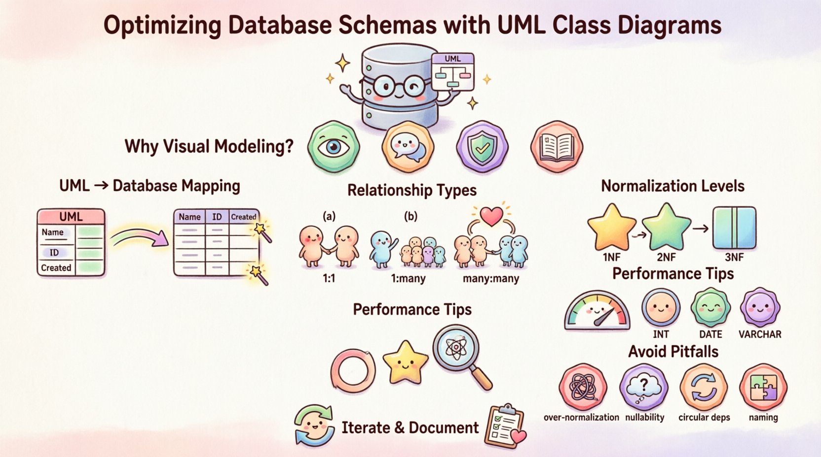
Why Visual Modeling Matters for Data 📊
Code is the execution, but design is the blueprint. Without a visual representation of how data entities relate to one another, teams often rely on mental models that drift apart as projects grow. UML Class Diagrams provide a standardized way to document system architecture. They force the consideration of attributes, relationships, and constraints early in the development lifecycle.
- Clarity: Stakeholders can visualize data flow without reading technical specifications.
- Communication: Developers, designers, and business analysts share a common vocabulary.
- Consistency: Enforces naming conventions and structural rules across the entire database.
- Documentation: Serves as living documentation that evolves with the codebase.
When applied to database schema optimization, these diagrams act as a bridge between abstract requirements and concrete storage mechanisms. They help identify redundant data, ambiguous relationships, and potential bottlenecks before implementation begins.
Core Components of a UML Class Diagram 🛠️
To effectively translate a UML diagram into a database schema, one must understand the specific elements involved. A class in object-oriented programming corresponds to a table in a relational database. However, the mapping requires careful attention to detail.
1. Classes and Tables
Every class defined in the diagram typically becomes a table in the database. The class name maps directly to the table name. For example, a class named User becomes a table named users. Attributes within the class become columns within the table.
2. Attributes and Data Types
Attributes define the properties of the entity. In a database context, these require specific data types. A UML attribute might be defined as String, but in the database, this translates to VARCHAR, TEXT, or CHAR depending on length and usage constraints. Precision matters here.
- Primary Keys: The unique identifier for a class instance. In UML, this is often marked with
+idor+PK. In the database, this becomes thePRIMARY KEY. - Foreign Keys: Attributes that link to another class. These enforce referential integrity.
- Visibility: Public attributes map to accessible columns, while private attributes might represent internal logic or hidden data.
3. Operations and Constraints
Operations in a class diagram represent methods. While database schemas do not store logic in columns, they do store constraints. Triggers, stored procedures, and check constraints often mirror the logic found in class operations. Identifying these during the modeling phase ensures the database enforces business rules automatically.
Mapping Relationships to Foreign Keys 🔗
Relationships are the backbone of a relational database. UML Class Diagrams excel at depicting these connections. Understanding cardinality is essential for optimizing schema performance and integrity.
One-to-One Relationships
This relationship occurs when a single instance of one class is linked to exactly one instance of another class. For example, a Person might have exactly one Passport.
- Implementation: Add a foreign key column in either table. Usually, the table with the optional side (if the relationship is not mandatory) holds the foreign key.
- Optimization: Consider merging tables if data is always accessed together to reduce join operations.
One-to-Many Relationships
This is the most common relationship type. A Customer can place many Orders, but each order belongs to only one customer.
- Implementation: Place the foreign key in the “many” side table (the
Orderstable). - Optimization: Index the foreign key column to speed up queries that retrieve orders for a specific customer.
Many-to-Many Relationships
Here, instances of one class relate to multiple instances of another, and vice versa. A Student can enroll in many Courses, and a Course can have many Students.
- Implementation: You cannot implement this directly in a relational database. You must create an associative table (junction table) to resolve the relationship.
- Optimization: Ensure the junction table has composite keys or appropriate indexes to handle lookups efficiently.
| Relationship Type | UML Notation | Database Implementation | Performance Note |
|---|---|---|---|
| One-to-One | 1..1 —- 1..1 | Foreign Key in one table | Consider table merge for access speed |
| One-to-Many | 1 —- * | Foreign Key in “many” table | Index foreign key column |
| Many-to-Many | * —- * | Intermediate junction table | Index both foreign keys in junction |
Normalization Strategies within UML 📉
Normalization is the process of organizing data to reduce redundancy and improve integrity. While UML diagrams focus on structure, the principles of normalization guide how attributes are distributed across classes.
First Normal Form (1NF)
Atomicity is key. Each column should contain only one value. In UML terms, this means avoiding complex object attributes that store lists or arrays directly in a single field unless the data type supports it natively and is queried efficiently.
- Check: Ensure attributes are not repeating groups.
- Example: Instead of a single
phone_numbersfield storing[123, 456], create a separatePhoneclass.
Second Normal Form (2NF)
All non-key attributes must be fully dependent on the primary key. If a class has a composite primary key, ensure no attribute depends on only part of that key. This often leads to splitting classes in the UML diagram to isolate specific data.
Third Normal Form (3NF)
Transitive dependencies should be removed. If attribute A determines B, and B determines C, then A determines C. In schema design, this means moving B to its own class if B is not part of A’s direct identity.
| Normalization Level | Rule | UML Impact |
|---|---|---|
| 1NF | No repeating groups | Split list attributes into separate classes |
| 2NF | No partial dependencies | Isolate attributes dependent on subsets of keys |
| 3NF | No transitive dependencies | Create new classes for dependent attributes |
Performance Considerations and Indexing ⚙️
While UML diagrams do not explicitly show database indexes, the structure they define dictates where indexes should be placed. Optimization involves balancing storage space against query speed.
- Query Patterns: Analyze how data will be retrieved. If a specific attribute is frequently used in search conditions, it should be indexed.
- Foreign Keys: Always index foreign key columns. Without them, joining tables becomes a full table scan, which is slow.
- Denormalization: Sometimes, strict normalization slows down reads. UML diagrams can help identify where denormalization is safe, such as storing a cached count of related items.
- Data Types: Choosing the correct data type in the diagram affects storage and performance. Use
INTinstead ofSTRINGfor IDs. UseDATEinstead ofSTRINGfor timestamps.
Common Pitfalls in Schema Design ❌
Even with a clear UML model, errors can occur during the translation to SQL. Awareness of common mistakes helps maintain a healthy schema.
1. Over-Normalization
Creating too many tables can make queries complex and slow. If a join involves five or more tables for a simple read, consider if some data could be combined. The UML diagram should reflect business logic, not just theoretical purity.
2. Ignoring Nullability
UML attributes often imply whether a value is required. In the database, this translates to NOT NULL constraints. Failing to map this correctly can lead to data integrity issues. Ensure optional attributes in the diagram map to nullable columns.
3. Circular Dependencies
A relationship where Class A depends on Class B, which depends on Class C, which depends back on Class A. While valid in some contexts, this can create circular reference errors during initialization or migration. Break these cycles in the design phase.
4. Inconsistent Naming
Using user_id in one table and UserId in another creates confusion. UML diagrams enforce consistency. Stick to a single naming convention, such as snake_case for tables and columns.
Iterative Design and Maintenance 🔄
Database schemas are not static. Requirements change, and the UML Class Diagram must evolve alongside the application. An optimized schema is one that can adapt without breaking existing functionality.
- Versioning: Keep versions of your UML diagrams to track changes over time.
- Refactoring: If a class grows too large, it may need to be split. This is a structural refactoring that requires careful migration planning.
- Review Cycles: Regularly audit the schema against the current UML model. Ensure the physical database matches the logical design.
- Backward Compatibility: When altering the schema, ensure new changes do not break existing queries or applications that rely on the old structure.
Best Practices for Documentation 📝
A well-maintained UML diagram is a form of documentation. It reduces the cognitive load on new team members and aids in troubleshooting.
- Legend: Include a legend explaining symbols used in the diagram, especially for visibility modifiers and inheritance.
- Annotations: Use notes in the diagram to explain complex constraints or business rules that are not immediately obvious.
- Metadata: Document the author, date of creation, and last modification date on the diagram.
- Consistency: Ensure the diagram matches the actual code. Drift between design and implementation renders the model useless.
Advanced Relationship Patterns 🧩
Beyond standard relationships, UML diagrams can model complex inheritance hierarchies and aggregations that impact the database schema significantly.
Inheritance and Polymorphism
When a Vehicle class has subclasses like Car and Truck, the database strategy changes. You can map this in three ways:
- Single Table: One table with a type discriminator column. Fastest reads, but sparse columns.
- Class Table: One table per class, joined together. Strict normalization, but complex joins.
- Concrete Table: Separate tables for each concrete subclass. No joins for specific types, but duplicate columns.
Aggregation and Composition
These relationships describe part-whole structures. Composition implies strong ownership (if the whole is deleted, the parts are deleted). Aggregation implies weak ownership. In the database, this often translates to cascading delete rules.
- Strong Ownership: Set
CASCADE DELETEon foreign keys. - Weak Ownership: Allow orphaned records or set
SET NULL.
Conclusion on Structural Integrity 🏁
Optimizing database schemas requires a blend of theoretical knowledge and practical application. UML Class Diagrams serve as the critical tool that connects business requirements to technical implementation. By rigorously defining classes, attributes, and relationships, teams can prevent common pitfalls such as redundancy, ambiguity, and performance bottlenecks.
The process is iterative. As the application grows, the model must be reviewed and refined. This ensures that the database remains a stable foundation rather than a source of technical debt. Focus on clarity, enforce constraints, and maintain documentation. These practices lead to systems that are easier to understand, faster to query, and simpler to maintain over the long term.
Investing time in the design phase pays dividends during development and operations. A well-modeled schema reduces the need for emergency fixes and refactoring later. It establishes a clear path for future expansion and ensures that data integrity remains intact as the application scales.

