


Software development relies heavily on the ability to translate abstract ideas into concrete structures. One of the most critical transitions in this process involves moving from natural language specifications to visual models. Specifically, converting text-based requirements into a UML class diagram allows architects and developers to visualize the static structure of a system before a single line of code is written. This process bridges the gap between what stakeholders want and how the system must behave.
Many teams struggle with this translation. Text is often ambiguous, while diagrams require precision. This guide explores the methodology for accurately converting specifications into a robust class model. We will examine how to identify entities, determine relationships, and map constraints without relying on external tools or buzzwords. The focus remains on the structural integrity and logical consistency of the design.
🧩 Why Text-to-Diagram Matters
Specifications are often written in prose, user stories, or requirement documents. While these formats are excellent for capturing intent, they lack the structural clarity needed for implementation. A UML class diagram serves as a blueprint. It defines:
- The distinct classes that exist within the domain.
- The attributes and data each class holds.
- The relationships between these classes.
- The constraints governing data flow and usage.
Without this visual representation, developers may interpret requirements differently. One developer might treat a “User” as a simple data object, while another might model it as a complex entity with authentication logic. A standardized diagram ensures everyone shares the same mental model of the system architecture.
📄 Understanding Your Input Specifications
Before drawing lines and boxes, you must thoroughly analyze the source material. Specifications can come in various forms, including:
- Functional Requirements: Descriptions of what the system should do.
- Non-Functional Requirements: Constraints like performance, security, or scalability.
- Domain Models: Existing documentation describing the business context.
- Use Case Narratives: Stories describing user interactions.
To extract meaningful data, read these documents with a specific focus on nouns and verbs. These grammatical elements often map directly to the components of a class diagram. However, context is king. The word “Bank” might refer to a financial institution (a class) or a physical location (an attribute). Understanding the domain context is essential for accurate modeling.
🏗️ Core Components of a UML Class Diagram
A class diagram consists of specific elements that represent the system’s structure. When converting text to diagram, you are essentially looking for these components:
- Class: A blueprint for objects. Identified by nouns in the text.
- Attribute: Data held within a class. Often found as adjectives or specific data fields.
- Operation: Methods or functions. Derived from verbs describing actions.
- Relationship: Connections between classes. Derived from verbs describing interactions.
- Multiplicity: Quantities involved in a relationship. Derived from quantifiers.
Each of these elements must be derived logically from the text. Guessing leads to technical debt later in the development cycle. Precision at this stage prevents costly refactoring.
🔄 Step-by-Step Conversion Methodology
Converting specifications to a diagram is a systematic process. Follow these steps to ensure accuracy and completeness.
1. Identify Potential Classes (The Noun Extraction)
Scan the requirements document for nouns. These are your candidate classes. However, not every noun becomes a class. Filter out:
- Common nouns that are too generic (e.g., “Thing”, “Object”).
- Nouns that represent attributes of another class (e.g., “Color” is usually an attribute of “Car”, not a class).
- Temporal concepts (e.g., “Time”, “Date” are often primitives).
Example: If the text says “A customer places an order,” “Customer” and “Order” are strong candidates for classes.
2. Define Attributes (The Property Identification)
Once a class is identified, look for details that describe it. Attributes represent the state of the object. Look for:
- Data types mentioned in the text (e.g., “integer”, “string”, “boolean”).
- Descriptive phrases (e.g., “The order has a unique ID”).
- Constraints on data (e.g., “Email must be valid”).
Attributes should be private by default in the diagram unless there is a clear reason for them to be public. This encapsulation is a core principle of object-oriented design.
3. Determine Operations (The Action Mapping)
Operations represent the behavior of the class. They are derived from the verbs in the specification. However, be careful not to model the entire system behavior here. The class diagram focuses on the structure that supports behavior, not the behavior itself.
- Look for verbs that imply a capability of the class.
- Identify methods that modify state (e.g.,
calculateTotal()). - Identify methods that retrieve state (e.g.,
getCustomerName()).
4. Map Relationships (The Connection Analysis)
This is the most complex part of the conversion. Relationships define how classes interact. The text usually contains prepositions or verbs that indicate these links.
- Association: General connection. “A User has an Address”.
- Aggregation: Weak ownership. “A Department has Employees” (Employees can exist without the Department).
- Composition: Strong ownership. “A House has Rooms” (Rooms cannot exist without the House).
- Inheritance: Specialization. “A Student is a Person”.
🔗 Analyzing Relationships and Multiplicity
Text descriptions rarely specify exact cardinality. You must infer this based on business rules. Multiplicity defines how many instances of one class relate to another.
Common multiplicity constraints include:
- One (1): Exactly one instance.
- Zero or One (0..1): Optional connection.
- One or More (1..*): Mandatory connection with no limit.
- Zero or More (0..*): Optional connection with no limit.
Example Analysis:
Consider the sentence: “A library book can be borrowed by multiple members, but a member can borrow multiple books at once. However, a specific copy of a book can only be borrowed by one person at a time.”
- Class A: Book
- Class B: Member
- Relationship: Borrowing
- Cardinality: Many-to-Many (0..* to 0..*)
Notice the nuance. The “specific copy” constraint might require a separate class like “Loan” to handle the transactional state, rather than a direct link between Book and Member. This is a critical decision when converting text to diagram.
🧬 Handling Inheritance and Polymorphism
Specifications often describe categories and subcategories. This indicates inheritance. Look for phrases like “is a type of,” “specialization of,” or “inherits from.”
- Generalization: The parent class represents common attributes and operations.
- Specialization: The child class adds specific attributes or overrides operations.
Caution: Do not create inheritance hierarchies unless there is a clear “is-a” relationship. “Has-a” relationships should be modeled as associations, not inheritance. For example, a “Car” has an “Engine,” but a “Car” is not an “Engine.”
✅ Validation and Consistency Checks
Once the diagram is drafted, you must validate it against the original text. This ensures nothing was missed and no assumptions were made incorrectly.
- Traceability: Can every class in the diagram be found in the requirements?
- Completeness: Are all relationships described in the text represented visually?
- Contradictions: Does the diagram allow a state that the text forbids? (e.g., Text says “Order must have an address,” Diagram allows null address).
- Granularity: Are classes too large or too small? Granularity affects maintainability.
This validation phase is not about perfection; it is about alignment. It ensures the visual model serves as a reliable contract for the development team.
📊 Text Indicators to UML Elements Mapping
Use the following table as a quick reference guide when analyzing text for diagram elements.
| Text Phrase / Concept | UML Element | Example |
|---|---|---|
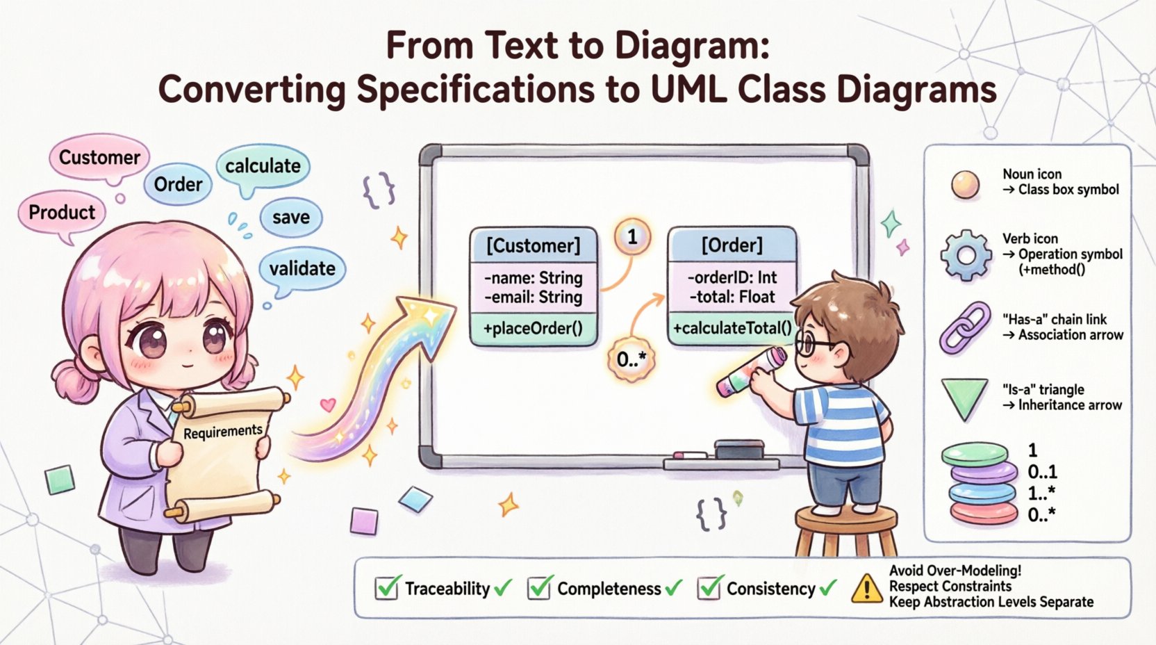
| Nouns (e.g., Customer, Invoice) | Class | class Customer { } |
| Adjectives / Data Types (e.g., email, price) | Attribute | - email: String |
| Verbs (e.g., calculate, save) | Operation | + calculateTotal(): float |
| “Has a” / “Contains” | Association / Composition | Line with diamond or open arrow |
| “Is a” / “Subtype of” | Inheritance | Line with hollow triangle |
| Quantifiers (e.g., one, many, all) | Multiplicity | 1, 0..*, 1..3 |
⚠️ Common Pitfalls to Avoid
Even experienced designers can make mistakes when translating text. Be aware of these common errors.
- Over-Modeling: Creating a class for every noun, including verbs or temporary states. Only model entities that have persistent state.
- Ignoring Constraints: Failing to represent mandatory fields or unique constraints. The diagram should reflect the rules of the domain.
- Mixing Levels of Abstraction: Combining database tables, user interface screens, and business logic classes in one diagram. Keep the domain model separate from the technical implementation details.
- Assuming Relationships: Assuming a relationship exists without textual evidence. If the text doesn’t say two classes interact, do not draw a line between them.
- Static vs. Dynamic Confusion: Trying to show sequence or flow in a class diagram. Class diagrams show structure, not time-based behavior.
🛠 Finalizing the Model
The final step is to ensure the diagram is clean and readable. A model that is too complex is useless. Apply these principles:
- Grouping: Use packages or compartments to group related classes logically.
- Naming: Ensure all class and attribute names are consistent with the terminology used in the specifications. Avoid technical jargon unless it aligns with the domain language.
- Visibility: Clearly mark public (+) and private (-) members if the diagram is intended for developer use.
- Documentation: Add notes or comments to the diagram to explain complex relationships that are not immediately obvious from the lines and boxes.
By following this structured approach, you transform vague text into a precise structural guide. This reduces ambiguity, aligns the team, and sets a solid foundation for the software implementation. The goal is not just to draw a picture, but to create a specification that drives development.
🚀 Key Takeaways
- Start with the text. Extract nouns for classes and verbs for relationships.
- Distinguish between association, aggregation, and composition based on ownership rules.
- Validate every element against the source requirements to ensure traceability.
- Keep the focus on structure, not behavior or implementation details.
- Use multiplicity to define the exact quantity constraints of relationships.
Converting specifications to UML class diagrams is a discipline that requires attention to detail and a deep understanding of domain logic. When done correctly, it serves as the backbone of a maintainable and scalable software system.

