


Software architecture relies heavily on how well we understand the problem space before writing a single line of code. At the heart of this understanding lies the domain model. A domain model represents the core concepts, behaviors, and rules of a specific business area. It serves as the blueprint for the system’s logic. However, abstract concepts can be difficult to communicate among stakeholders, developers, and analysts. This is where the Unified Modeling Language (UML) Class Diagram becomes an essential tool.
Class diagrams provide a static view of a system, capturing structure rather than behavior. They allow teams to visualize entities, attributes, and relationships in a standardized format. When used correctly, these diagrams reduce ambiguity and align technical implementation with business requirements. Precision in visualization ensures that the resulting code remains maintainable and robust over time.
Foundations of Domain Modeling 🧠
Before drawing lines and boxes, one must understand the purpose of the model. A domain model is not a database schema. It is a representation of the business logic. Confusing the two leads to systems that are rigid and difficult to adapt. The primary goal is to capture the essence of the business rules.
Key principles include:
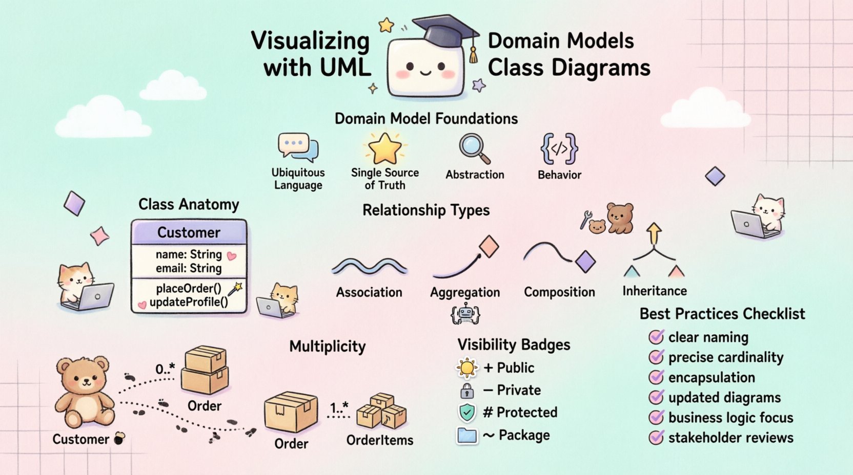
- Ubiquitous Language: Use terms that stakeholders understand naturally.
- Single Source of Truth: The model should reflect the agreed-upon logic.
- Abstraction: Focus on essential concepts, ignoring irrelevant details.
- Behavior: Include operations that define how entities act.
By adhering to these principles, the diagram becomes a communication tool rather than just a technical artifact. It bridges the gap between non-technical business owners and technical engineers.
Anatomy of a Class Diagram 🏗️
Understanding the components of a class is fundamental to creating accurate diagrams. Each class typically consists of three compartments. The top compartment holds the name. The middle holds attributes. The bottom compartment holds methods or operations. Proper separation ensures clarity.
Class Names
Class names should be nouns representing entities within the domain. They must be capitalized using PascalCase. For example, Customer or Order are standard conventions. Avoid generic names like Item unless the context is strictly defined. Clarity in naming prevents confusion during implementation.
Attributes
Attributes define the state of an object. They should be typed and have a defined scope. For instance, a Customer might have a name (String) and an age (Integer). Visibility modifiers are crucial here. Private attributes are internal, while public attributes are accessible externally. This distinction protects data integrity.
Operations
Operations define the behavior. They are methods that manipulate the state of the class. An Order class might have an calculateTotal() operation. Operations should also have visibility modifiers. Private operations are helper functions, while public operations form the interface for other classes.
Managing Relationships 🔗
Classes rarely exist in isolation. They interact with other classes through relationships. These relationships define how objects are connected and how they influence one another. There are several types of relationships, each with a specific meaning and notation.
| Relationship Type | Notation | Meaning |
|---|---|---|
| Association | Solid Line | General connection between classes. |
| Aggregation | Hollow Diamond | Whole-Part relationship where parts can exist independently. |
| Composition | Filled Diamond | Strong Whole-Part relationship where parts cannot exist independently. |
| Inheritance | Arrow with Hollow Triangle | Generalization where a child class inherits from a parent. |
Understanding the difference between Aggregation and Composition is critical. In Aggregation, a Department has Employees, but if the department closes, the employees still exist. In Composition, a House has Rooms. If the house is demolished, the rooms cease to exist. This distinction impacts how data is managed and persisted.
Cardinality and Multiplicity
Relationships are not just binary. They often involve quantities. Multiplicity defines how many instances of one class relate to another. Common notations include:
- 1: Exactly one instance.
- 0..1: Zero or one instance.
- 1..*: One or more instances.
- *: Many instances (same as 0..*).
For example, a Customer places 0..* Orders. A single Order contains 1..* OrderItems. This precision prevents logical errors during database design and coding.
Inheritance Strategies 🔄
Inheritance allows classes to share common attributes and behaviors. It promotes code reuse and establishes a hierarchy. However, it must be used judiciously. Overuse can lead to deep hierarchies that are hard to maintain.
When designing inheritance:
- Is-A Relationship: Ensure the child class truly is a type of the parent. A
Caris aVehicle. ACaris not aWheel. - Abstraction: Use abstract classes for concepts that cannot be instantiated, like
PaymentMethod. - Polymorphism: Allow different classes to respond to the same method call differently.
Consider the trade-offs. Inheritance creates tight coupling. If the parent changes, the children might break. Alternatives like composition can sometimes be more flexible. The decision depends on the stability of the domain model.
Visibility and Scope 👁️
Visibility controls access to class members. It is a fundamental aspect of encapsulation. There are four standard visibility levels.
- Public (+): Accessible from anywhere. Use sparingly for interfaces.
- Private (-): Accessible only within the class. Protects internal state.
- Protected (#): Accessible within the class and subclasses.
- Package (~): Accessible within the same package or namespace.
Defaulting to private visibility is a safe practice. It exposes only what is necessary through public operations. This minimizes the risk of unintended side effects. It also makes the class easier to refactor later.
Common Modeling Mistakes ⚠️
Even experienced practitioners make errors. Identifying these pitfalls early saves significant time during development.
- Database-Centric Design: Modeling tables instead of objects. This ignores business logic and behavior.
- Over-Engineering: Creating too many relationships or abstract classes. Keep it simple.
- Ignoring Multiplicity: Forgetting to define how many objects are linked. This leads to null pointer exceptions.
- Inconsistent Naming: Mixing singular and plural nouns or camelCase and PascalCase.
- Lack of Documentation: Diagrams without context or notes are useless to future maintainers.
Reviewing the model with a fresh perspective helps catch these issues. Peer reviews are essential for maintaining quality.
Iterative Refinement Process 🔄
Domain models evolve. Requirements change, and new features are added. The diagram should reflect this evolution. A static model is a dead model.
The refinement process involves:
- Validation: Check if the model matches business rules.
- Optimization: Remove redundant classes or relationships.
- Standardization: Ensure all diagrams follow the same notation standards.
- Versioning: Track changes to the model over time.
Regular updates ensure the documentation remains accurate. This alignment prevents the drift between design and implementation.
Collaboration and Documentation 🤝
A diagram is only as good as the understanding it fosters. It must be accessible to all team members. Clear notation and consistent style are vital.
- Contextual Notes: Add comments to explain complex logic.
- Legibility: Arrange classes to minimize line crossings.
- Tooling: Use standard tools that support export and version control.
- Integration: Link diagrams to code repositories for traceability.
When everyone understands the model, collaboration becomes smoother. Misunderstandings are reduced, and development velocity increases.
Bridging Models to Code 🧩
The ultimate goal is to translate the visual model into working software. This translation should be as direct as possible. Code generators can help, but manual implementation is often necessary for complex logic.
Best practices for this transition include:
- Consistency: Ensure code structure matches the diagram structure.
- Comments: Use code comments to reference specific model elements.
- Testing: Write tests based on the behavior defined in the operations.
- Refactoring: If the code changes significantly, update the diagram.
This feedback loop ensures the documentation remains a true reflection of the system.
Maintaining Clarity Over Time 🌱
As systems grow, diagrams can become cluttered. Managing complexity is an ongoing task. Strategies include:
- Subsystems: Group related classes into packages.
- Profiles: Use stereotypes to denote specific types of classes.
- Layers: Separate presentation, business, and data layers.
By organizing the model logically, you preserve its readability. This ensures that the diagram remains a useful tool throughout the lifecycle of the project.
Summary of Best Practices ✅
- Use clear, domain-specific naming conventions.
- Define relationships with precise cardinality.
- Respect encapsulation through visibility modifiers.
- Keep diagrams updated with code changes.
- Focus on business logic, not just database tables.
- Review models with stakeholders regularly.
Following these guidelines leads to systems that are easier to build and easier to change. Precision in visualization is not just about drawing lines; it is about thinking clearly about the problem.

