


In the modern software landscape, the majority of development occurs across different geographical locations. This shift has fundamentally altered how technical documentation is created, reviewed, and maintained. Among the various modeling techniques available, the Unified Modeling Language (UML) Class Diagram remains a cornerstone for defining system structure. However, leveraging these diagrams effectively within a distributed environment requires more than just drawing boxes and lines. It demands a rigorous approach to communication, standardization, and version management.
This guide explores the practical application of UML Class Diagrams when teams are not co-located. We will examine the anatomy of the diagram, the specific challenges of remote collaboration, and the workflows necessary to maintain a single source of truth for system architecture.
🧱 Understanding the Foundation of Class Diagrams
A UML Class Diagram is a static structural diagram. It depicts the system’s classes, their attributes, operations, and the relationships among objects. In a distributed setting, this diagram acts as the primary contract between architects, developers, and stakeholders who may never share a physical space.
When building a class diagram remotely, clarity is paramount. Ambiguity leads to implementation errors, which are significantly more costly to fix in a distributed workflow than in a co-located one.
Core Components to Define
- Class Name: The identifier for the entity. It must follow a strict naming convention agreed upon by the entire team.
- Attributes: The data properties held within the class. Visibility modifiers (public, private, protected) are critical for defining encapsulation boundaries.
- Operations: The methods or functions the class exposes. These define the behavior and interaction points.
- Relationships: The links between classes, such as association, inheritance, or dependency. These define the topology of the system.
Without a shared understanding of these components, team members in different time zones will interpret the model differently. This results in divergent implementations that fail to integrate smoothly.
🏗️ Key Components of a Class Diagram
To ensure consistency across a global team, every element within the diagram must be defined with precision. The following breakdown details the specific elements that require strict governance.
- Visibility Markers: Use + for public, – for private, and # for protected. These symbols are universal but must be consistently applied in every diagram produced.
- Multiplicity: Indicate the number of instances allowed (e.g., 0..1, 1..*, 0..*). Misinterpreting multiplicity is a common source of logic errors in distributed teams.
- Roles: Assign names to the ends of associations to clarify the direction of the relationship.
- Interfaces: Use interface symbols (<
>) to define contracts that allow different classes to interact without tight coupling.
Standardizing these elements reduces the cognitive load on developers. When a developer in Tokyo views a diagram created by an architect in New York, the symbols should mean exactly the same thing.
🌍 Challenges in Distributed Environments
Remote modeling introduces specific friction points that do not exist in co-located settings. Understanding these barriers is the first step toward mitigating them.
1. Asynchronous Communication Gaps
In an office, a developer can walk over to an architect to clarify a line on a whiteboard. In a distributed team, this interaction takes time. Emails, tickets, and comments create latency.
- Latency: Waiting for feedback on a diagram change can stall development for days.
- Context Loss: Text-based comments often lack the nuance of a verbal conversation. A simple arrow on a diagram can be interpreted in multiple ways without immediate clarification.
2. Version Control Conflicts
Unlike code, diagrams are often visual files. Merging changes from multiple authors simultaneously can lead to file corruption or overwriting. If two architects modify the same class diagram at the same time, the result is often a conflict that requires manual resolution.
3. Cultural and Terminological Differences
Terms like “Entity,” “Object,” or “Service” can mean different things in different business units or regions. A distributed team must agree on a shared glossary before drawing a single class.
📏 Establishing Modeling Conventions
To overcome these challenges, a team must establish a robust set of conventions. These rules serve as the governance framework for all modeling activities.
Naming Standards
- PascalCase: Use PascalCase for class names (e.g.,
OrderProcessor). - camelCase: Use camelCase for attributes and methods (e.g.,
calculateTotal). - Avoid Abbreviations: Unless standard industry acronyms, write terms in full to avoid ambiguity.
Diagram Scope and Granularity
One of the biggest mistakes in distributed modeling is creating monolithic diagrams. A single file containing every class in a large system is difficult to review asynchronously.
- Package Diagrams: Use package diagrams to show high-level groupings of classes.
- Subsystem Diagrams: Create separate class diagrams for specific subsystems or domains.
- Context Diagrams: Provide a top-level view showing how the system interacts with external actors.
🔗 Managing Relationships and Dependencies
The relationships between classes are the most critical part of the diagram for maintaining system integrity. In a distributed team, changes to relationships can have cascading effects across the codebase.
Types of Relationships
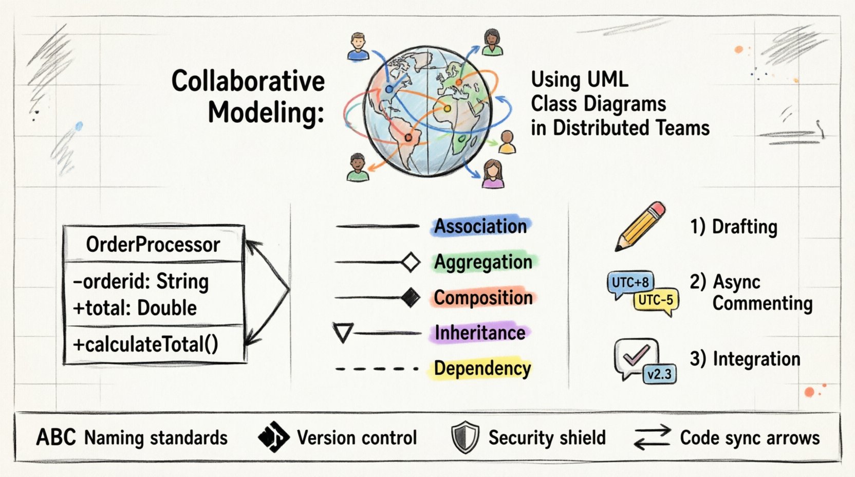
| Relationship Type | Symbol | Meaning in Remote Context |
|---|---|---|
| Association | Solid Line | A structural link where one class knows about another. |
| Aggregation | Hollow Diamond | A “has-a” relationship where parts can exist independently. |
| Composition | Filled Diamond | A strong “part-of” relationship where lifetimes are tied. |
| Inheritance | Hollow Triangle | An “is-a” relationship indicating polymorphism. |
| Dependency | Dashed Line | A usage relationship where one class relies on another. |
Dependency Management
Dependencies create coupling. In a distributed team, high coupling increases the risk of breaking changes. Teams should aim for loose coupling.
- Minimize Direct Dependencies: Use interfaces to decouple implementation from usage.
- Document Dependencies: Clearly mark external dependencies on the diagram to prevent circular references.
- Review Impact: Before modifying a class, review all dependent classes to assess the scope of the change.
⏳ Workflow for Distributed Review
A structured review workflow ensures that diagrams remain accurate without requiring synchronous meetings. This process replaces the “walk-around” review with a formalized digital process.
1. Drafting Phase
The architect or lead developer creates the initial model. This draft should be treated as a proposal, not a final specification.
- Ensure all classes are named according to conventions.
- Verify that all attributes and operations are defined.
- Check for completeness in relationships.
2. Asynchronous Commenting
Instead of a live meeting, the diagram is published to a shared repository. Team members review the document individually and leave comments.
- Comment Specificity: Comments should reference specific elements (e.g., “Class A, Attribute B”) rather than general feedback.
- Time Zone Rotation: Rotate the responsibility of the first reviewer to accommodate different time zones.
- Resolution Tracking: Every comment must be either resolved, deferred, or rejected with a reason.
3. Integration Phase
Once feedback is incorporated, the diagram is updated. The updated version is then published for a final sanity check by the core team.
- Update the version number in the diagram footer.
- Update the change log to document what was modified and why.
- Notify the team of the final approval via a standard communication channel.
🔄 Version Control for Visual Models
Just as code is managed in version control systems, diagrams should be treated as code. This practice, often called “Model-as-Code,” ensures traceability and history.
Commit Strategies
- Atomic Commits: Make small, logical changes rather than rewriting entire diagrams.
- Descriptive Messages: Use commit messages that explain the intent of the change (e.g., “Refactor Order class to support multiple currencies”).
- Branching: Use feature branches for major modeling changes to prevent blocking other team members.
Diffing and Merging
Visual files are notoriously difficult to merge. To address this:
- Text-Based Formats: Prefer diagram formats that are text-based (such as XMI or specific domain-specific languages) over binary image formats.
- Change Logs: Maintain a separate text document detailing significant changes for quick reference.
- Automated Checks: Implement scripts to validate diagram syntax before merging to prevent corruption.
⚠️ Common Pitfalls to Avoid
Even with a solid process, distributed teams often fall into traps that degrade the quality of the modeling effort.
1. Over-Engineering the Diagram
Creating a diagram that shows every possible edge case is often counterproductive. A diagram should represent the current design intent, not every theoretical possibility.
- Focus on Core Logic: Prioritize the critical paths of the system.
- Iterate: Refine the diagram as the system evolves rather than trying to predict the future.
2. Ignoring the Code Reality
There is a tendency to let the diagram drift away from the actual code. In a distributed team, this drift is harder to catch.
- Reverse Engineering: Periodically generate the diagram from the codebase to identify discrepancies.
- Code Generation: Where possible, generate code from the diagram to ensure they stay in sync.
- Regular Audits: Schedule quarterly reviews to align the model with the implementation.
3. Lack of Context
New team members may struggle to understand the diagram without context. In a remote setting, onboarding is already difficult.
- Documentation: Accompany diagrams with a brief text description of the domain logic.
- Examples: Include sequence diagrams that show how the classes interact in a specific scenario.
- Glossary: Maintain a living document that defines terms used in the diagrams.
🛡️ Security and Confidentiality in Shared Models
Class diagrams often reveal the internal structure of a system. In a distributed environment, access control becomes critical.
- Access Levels: Restrict access to diagrams based on the team member’s role. Not everyone needs to see the database schema.
- Data Masking: If diagrams contain sensitive field names, consider using generic names in public-facing models.
- Audit Trails: Keep logs of who viewed and modified the diagrams to ensure accountability.
📈 Integrating with Development Pipelines
The diagram should not exist in a vacuum. It must integrate with the continuous integration and deployment processes.
- Validation Gates: Include diagram syntax checks in the build pipeline to prevent invalid models from being merged.
- Artifact Generation: Ensure that the build process can produce the necessary documentation from the model.
- Traceability: Link diagram elements to user stories or requirements tickets to track progress.
🤝 Building a Collaborative Culture
Finally, the tools and processes are secondary to the culture of the team. Successful collaborative modeling relies on trust and open communication.
- Encourage Feedback: Make it safe for junior developers to question the architecture of senior engineers.
- Rotate Ownership: Allow different team members to own different parts of the model to prevent bottlenecks.
- Celebrate Updates: Acknowledge when the model is successfully updated and integrated into the codebase.
Summary
Implementing UML Class Diagrams in a distributed team requires a shift from informal sketching to formalized engineering. By establishing strict conventions, utilizing version control, and managing the review process asynchronously, teams can maintain a high-fidelity view of their system architecture.
The goal is not perfection in the diagram, but clarity in communication. When every team member understands the structure and relationships defined in the model, the distance between them becomes irrelevant. This approach enables the development of robust, scalable systems regardless of where the developers are located.
Focus on the standards, respect the process, and keep the model synchronized with the code. This discipline ensures that the visual representation of your system remains a reliable guide for everyone involved.

