


Building software that grows without breaking requires more than just writing efficient code. It demands a structured approach to architecture, where the blueprint precedes the construction. UML class diagrams serve as this blueprint, offering a visual representation of the system’s static structure. When used correctly, they become the foundation for scalability, allowing teams to anticipate bottlenecks before a single line of production code is written. This guide explores how to leverage these diagrams to design systems capable of handling increased load, complexity, and change.
Why Structure Matters Before Implementation 📐
Many development teams rush into coding without a clear mental model of how components interact. This often leads to tight coupling, where changes in one module force ripple effects across the entire system. In the early stages of a project, the cost of fixing architectural flaws is minimal. As the system matures, those costs compound exponentially. UML class diagrams provide a neutral ground for discussion, allowing architects, developers, and stakeholders to align on responsibilities and relationships.
Scalability is not merely about server capacity; it is about code organization. A system designed with clear boundaries can scale horizontally by adding more instances of specific components. A system with hidden dependencies will fail when load increases because the underlying logic cannot distribute the work. Diagrams help identify these hidden dependencies by forcing the designer to explicitly state how objects connect.
Core Components of a Class Diagram 🧩
Understanding the building blocks is essential before attempting to construct a scalable model. Every class diagram consists of specific elements that define behavior and state. Clarity in these elements ensures that the resulting code is maintainable.
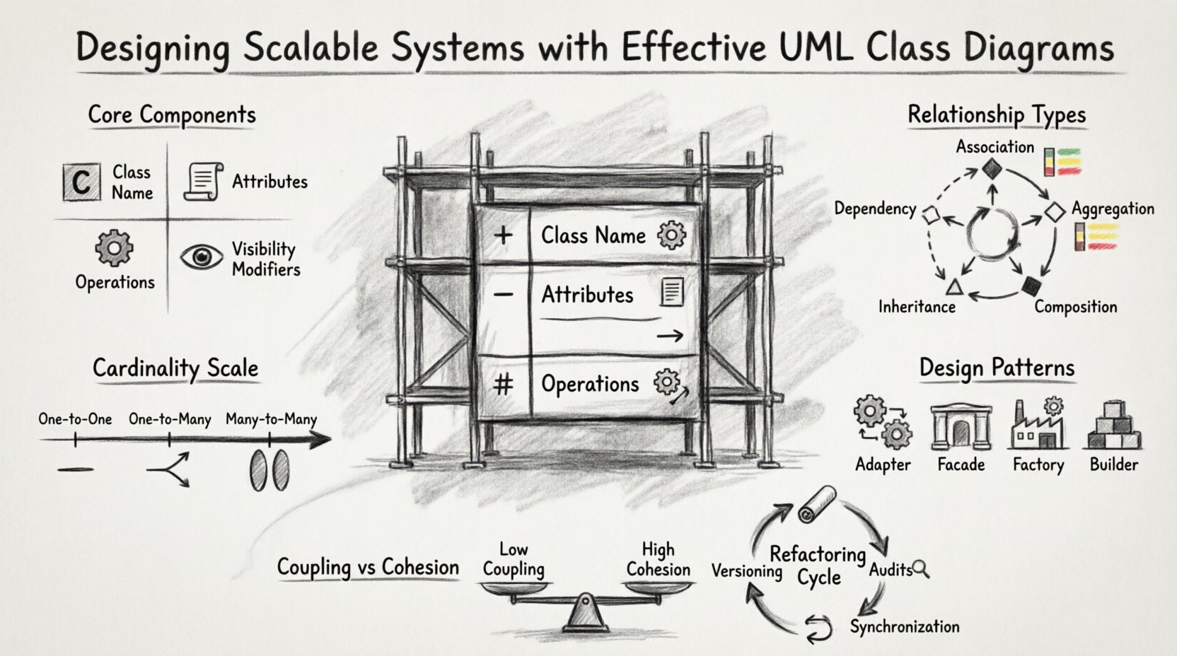
- Class Name: Identifies the entity within the system. It should be a noun, singular, and clearly defined.
- Attributes: Represent the state or data held by the class. In scalable designs, these should be minimized to reduce memory footprint.
- Operations: Represent the methods or functions the class can perform. Operations should be specific to the class’s responsibility.
- Visibility Modifiers: Define access levels. Using public, private, and protected modifiers correctly prevents external classes from manipulating internal data improperly.
When designing for scale, every attribute and operation must justify its existence. If a class holds data that is rarely accessed, it may be a candidate for a separate service or a lazy-loading strategy. The diagram should reflect these decisions visually.
Understanding Relationships and Their Impact on Scalability 🔗
Relationships define how classes interact. In a scalable system, the type of relationship determines the degree of coupling. High coupling reduces flexibility, making it difficult to modify or replace components. Low coupling allows components to be swapped or scaled independently.
Key Relationship Types
Not all connections are created equal. Some are necessary, while others introduce fragility. Below is a breakdown of how different relationships affect system design.
| Relationship | Description | Scalability Impact |
|---|---|---|
| Association | A structural link between two classes. | Neutral if managed; high cardinality can create performance bottlenecks. |
| Aggregation | A “whole-part” relationship where parts can exist independently. | Good for loose coupling; allows parts to be scaled or replaced without stopping the whole. |
| Composition | A strong ownership where parts cannot exist without the whole. | Ensures data integrity but increases dependency; use sparingly in distributed systems. |
| Inheritance | A “is-a” relationship sharing behavior. | Can lead to deep hierarchies; deep inheritance chains are hard to maintain at scale. |
| Dependency | A temporary usage relationship. | Indicates tight coupling; should be minimized to reduce side effects. |
Managing Cardinality
Cardinality defines how many instances of one class relate to another. For example, a one-to-many relationship means one user can have many orders. In scalable designs, understanding this ratio is critical.
- One-to-One: Simple but often indicates data duplication or a need for database normalization.
- One-to-Many: Common in transactional systems. Ensure indexes are planned based on these relationships.
- Many-to-Many: Requires an intermediate class or join table. This adds complexity and must be modeled carefully to avoid query performance issues.
When a relationship creates a high cardinality, it often signals a need for caching or asynchronous processing. The diagram should highlight these connections so developers know where to apply optimization strategies.
Design Patterns Represented in Class Models 🧠
Design patterns are proven solutions to common problems. Embedding these patterns into class diagrams ensures that the architecture follows established best practices for growth. Visualizing patterns helps teams recognize structural flaws early.
Structural Patterns
- Adapter: Allows incompatible interfaces to work together. In diagrams, show the adapter class bridging two distinct systems.
- Facade: Provides a simplified interface to a complex subsystem. This reduces the number of dependencies a client must know.
- Proxy: Controls access to an object. Useful for lazy loading or security checks without changing the core logic.
Creational Patterns
- Factory Method: Delegates instantiation to subclasses. This makes the system extensible without modifying existing code.
- Builder: Constructs complex objects step-by-step. Useful when objects have many optional parameters.
- Singleton: Ensures only one instance exists. Use with caution in distributed environments, as it can create hidden global state.
When a pattern is applied, the class diagram should explicitly show the participating classes. For instance, a Factory pattern diagram should clearly distinguish between the Creator, the Concrete Product, and the Client. This visibility prevents developers from hardcoding instantiation logic later.
Managing Coupling and Cohesion for Growth 📈
Coupling and cohesion are the twin pillars of maintainable architecture. Coupling measures the degree of interdependence between modules. Cohesion measures how closely related the responsibilities of a single module are.
High Cohesion
A class with high cohesion has a single, well-defined purpose. All attributes and methods contribute to that purpose. High cohesion makes classes easier to test, reuse, and replace. In a diagram, high cohesion looks like a class with a focused name and a tight set of methods.
- Focus on the Single Responsibility Principle.
- Group related data and behavior together.
- Avoid “God Classes” that do too many things.
Low Coupling
Low coupling means a class knows little about the internal details of other classes. It interacts through interfaces or abstract classes. This allows you to change the implementation of one class without affecting others.
- Use interfaces to define contracts.
- Inject dependencies rather than creating them internally.
- Avoid direct access to private members of other classes.
The goal is to design a system where components are loosely connected. If one component fails or needs an upgrade, the rest of the system remains stable. Diagrams should clearly show the interfaces being implemented, rather than concrete classes being referenced.
Refactoring Diagrams as Systems Evolve 🔄
Software is never static. Requirements change, technologies evolve, and new constraints appear. A class diagram is a living document that must evolve alongside the code. Keeping the diagram up to date is a discipline that pays off during refactoring.
Versioning the Model
Just as code is versioned, the model should be tracked. Major changes in architecture should correspond to a new version of the diagram. This helps teams understand the history of decisions and why certain structures were chosen.
- Document the rationale behind major structural changes.
- Mark deprecated classes or relationships clearly.
- Keep a changelog for architectural diagrams.
Identifying Refactoring Opportunities
As the system grows, certain patterns may emerge that indicate the need for restructuring. Look for the following signs in the diagram:
- Duplicate Classes: If two classes perform similar functions, consider merging them.
- Long Inheritance Chains: Deep hierarchies are hard to navigate. Flatten them using composition.
- Circular Dependencies: Class A depends on Class B, which depends on Class A. This creates a cycle that prevents independent deployment.
- God Classes: Classes that have grown too large and handle too many responsibilities.
When refactoring, update the diagram first. This ensures the team understands the target state before writing the code. It prevents the “spaghetti code” scenario where the implementation drifts away from the intended design.
Collaboration and Documentation Standards 🤝
A diagram is only useful if the team understands it. Standardizing notation and documentation ensures that every developer reads the model in the same way. This is crucial for onboarding new members and maintaining consistency across large codebases.
Standard Notation
Adhere strictly to the Unified Modeling Language (UML) standards. Deviating from standard notation creates confusion. Ensure that everyone on the team uses the same symbols for visibility, types, and relationships.
- Use `+` for public, `-` for private, and `#` for protected.
- Use `<
>` to denote interfaces. - Keep class names in TitleCase.
- Use singular names for classes and plural for collections.
Documentation Best Practices
Text annotations within the diagram can clarify intent. However, do not clutter the visual model with excessive text. Use notes for complex logic or business rules that cannot be expressed through relationships.
- Keep descriptions concise.
- Link diagrams to code repositories where possible.
- Review diagrams during code reviews to ensure alignment.
Maintaining Diagram Accuracy Over Time 📅
The most common failure in model-driven development is the divergence between the diagram and the code. If the diagram is outdated, it becomes misleading and eventually ignored. Maintaining accuracy requires a culture of discipline.
Automated Synchronization
Where possible, use tools that can generate diagrams from code or vice versa. This ensures that the visual model reflects the actual implementation. While manual updates are still necessary for high-level design, automated generation prevents syntax errors.
- Enable auto-generation in development environments.
- Set up CI/CD pipelines to validate diagram consistency.
- Use annotations in code to document diagram intent.
Regular Audits
Schedule periodic reviews of the architecture. Ask the following questions:
- Does the diagram match the current codebase?
- Are there any deprecated classes still referenced?
- Has the system grown in a way that violates the original design principles?
These audits prevent technical debt from accumulating silently. They ensure that the visual representation remains a reliable source of truth for the system’s structure.
Conclusion on Design Discipline 🎯
Designing scalable systems is a continuous process of balancing structure and flexibility. UML class diagrams are the tool that makes this balance visible. They allow teams to discuss architecture without the noise of implementation details. By focusing on relationships, patterns, and maintenance, developers can build systems that withstand the test of time and growth.
The effort invested in creating accurate diagrams pays dividends during the development lifecycle. It reduces rework, clarifies communication, and provides a roadmap for future expansion. When the diagram is respected, the code follows suit, resulting in a robust and adaptable software architecture.

