


Understanding the structure of software is a fundamental skill for any developer or architect. One of the most effective tools for visualizing this structure is the Unified Modeling Language (UML) Class Diagram. Despite its widespread use, many professionals still find specific elements confusing or struggle with when to apply certain notations. This guide addresses common inquiries to clarify the syntax and semantics of class modeling.
🔍 What Exactly Is a UML Class Diagram?
A UML Class Diagram is a static structure diagram that describes the system’s structure by showing its classes, their attributes, operations, and the relationships among objects. Unlike sequence diagrams, which focus on behavior over time, class diagrams provide a blueprint of the system at a specific point in time.
- Purpose: To model the static view of an application.
- Components: Classes, interfaces, attributes, and methods.
- Benefit: It helps teams communicate design decisions before writing code.
Think of it as the architectural floor plan for a building. You wouldn’t start constructing without a plan that shows where the load-bearing walls are; similarly, you shouldn’t start coding without understanding how your classes interact.
🏗️ Core Components Explained
Every class diagram is built upon a few standardized elements. Understanding these building blocks is essential for accurate modeling.
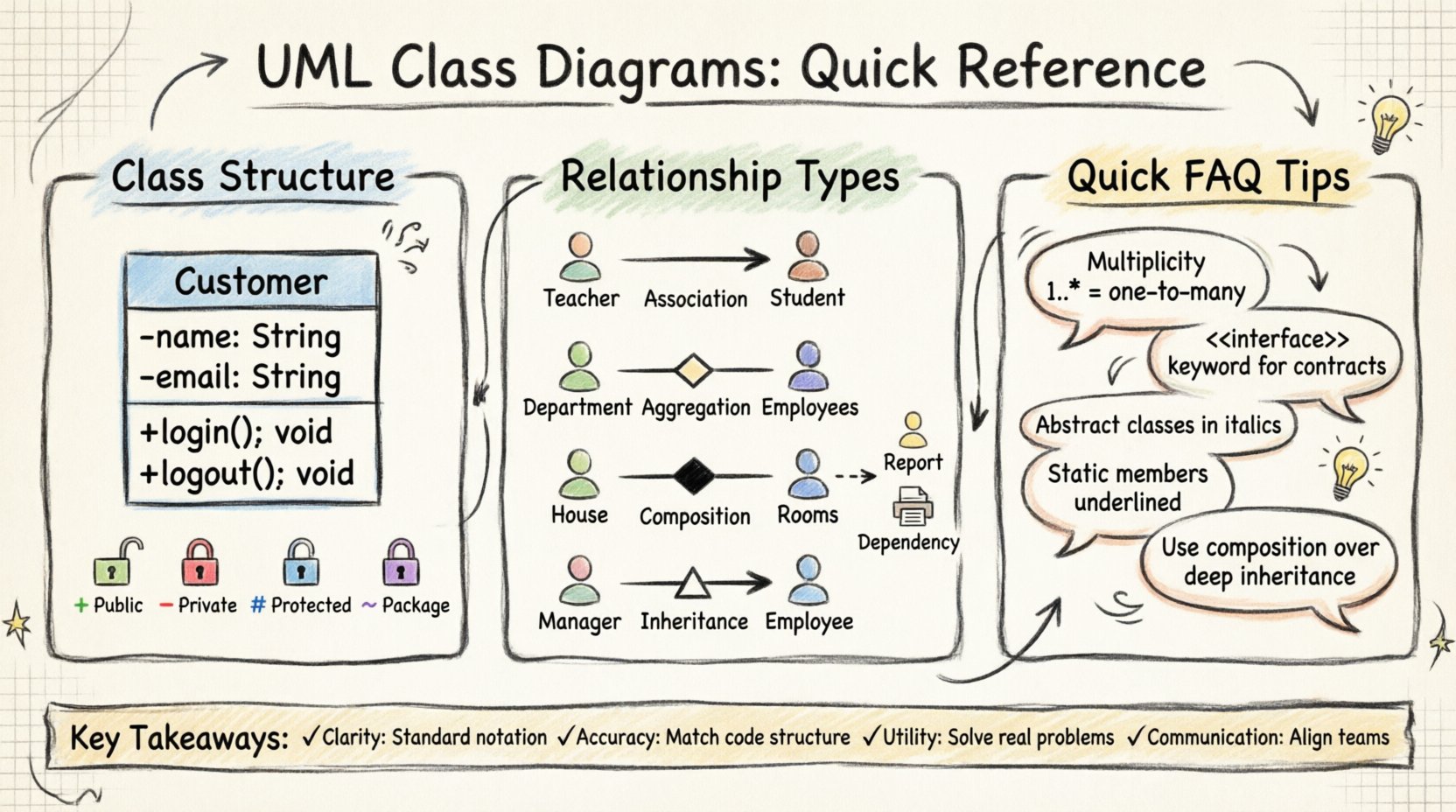
1. The Class Rectangle
A class is typically represented by a rectangle divided into three sections:
- Name: The top section contains the class name (e.g.,
Customer). - Attributes: The middle section lists properties (e.g.,
name: String). - Operations: The bottom section lists methods or functions (e.g.,
+ login(): void).
2. Visibility Modifiers
Before a property or method name, symbols indicate accessibility:
- +: Public – Accessible from anywhere.
- -: Private – Accessible only within the class.
- #: Protected – Accessible within the class and subclasses.
- ~: Package-private – Accessible within the same package.
3. Multiplicity
Numbers or ranges placed near the ends of association lines define how many instances of a class relate to another. For example, 1..* means one to many.
🔗 Navigating Relationships
Relationships define how classes interact. Confusion often arises here, particularly between aggregation and composition. The table below clarifies the distinctions.
| Relationship Type | Symbol | Meaning | Example |
|---|---|---|---|
| Association | Solid Line | A general link between classes. | A Teacher teaches a Student. |
| Aggregation | Hollow Diamond | Whole-part relationship where parts can exist independently. | A Department has Employees. |
| Composition | Filled Diamond | Strong ownership; parts cannot exist without the whole. | A House has Rooms. |
| Inheritance (Generalization) | Triangle Arrow | One class is a specialized version of another. | Manager extends Employee. |
| Dependency | Dashed Line | One class uses another temporarily. | A Report uses a Printer. |
Understanding these nuances prevents structural errors in software design. For instance, if you model a Car as owning an Engine via aggregation, the Engine could theoretically exist without the Car. If it is composition, destroying the Car destroys the Engine.
❓ Frequently Asked Questions
We have compiled the most frequent questions regarding UML Class Diagrams to provide clarity on implementation and design.
Q1: Can I draw class diagrams without specialized software?
Yes. While modeling tools exist, the diagram is a conceptual artifact. You can sketch these on paper, whiteboards, or use basic text editors to represent the structure. The goal is communication, not aesthetic perfection. However, digital tools offer version control and auto-generation features which can streamline the process for large projects.
Q2: How do I represent interfaces in a class diagram?
Interfaces are drawn as a rectangle with the keyword <
Q3: What is the difference between an abstract class and an interface?
An abstract class can contain both abstract methods (no body) and concrete methods (with body). It supports state through attributes. An interface traditionally only defines contracts (methods) but modern standards allow default implementations. Use abstract classes for shared code and interfaces for defining capabilities across unrelated classes.
Q4: How should I handle inheritance hierarchies?
- Keep it shallow: Deep hierarchies are hard to maintain.
- Use composition: Often, combining objects is better than extending a base class.
- One parent: Most languages support single inheritance for classes to avoid ambiguity.
Q5: When should I use multiplicity?
Multiplicity is critical for defining constraints. If a User can have multiple orders, the relationship is 1..*. If an Order must have exactly one User, it is 1. Omitting this leads to runtime errors where assumptions about data quantity are incorrect.
Q6: Do attributes need data types?
Yes. Including data types (e.g., Integer, Boolean, Date) clarifies the nature of the data. It reduces ambiguity for developers translating the model into code. If a type is unknown, Object or a generic type can be used, but specificity is preferred.
Q7: How do I model a many-to-many relationship?
A direct line between two classes implies a relationship. For many-to-many (e.g., Students and Courses), an association line connects them with * on both sides. In database terms, this often requires an intermediate table (associative entity). In modeling, you might introduce a class to manage this intersection if additional attributes are needed.
Q8: What about static members?
Static members belong to the class itself rather than an instance. They are typically underlined in the class diagram. For example, a Counter class might have a static getInstance() method. This is useful for singleton patterns or utility classes.
Q9: Can I show private attributes in a class diagram?
Technically, yes, but it depends on the audience. For internal developer documentation, showing private details aids understanding. For high-level architectural views, hiding internal complexity (using public interfaces) keeps the diagram readable. Consistency across the project is key.
Q10: How does this differ from an Entity-Relationship Diagram (ERD)?
ERDs focus on database tables and constraints. UML Class Diagrams focus on object-oriented design and behavior. While they look similar, UML includes methods and visibility modifiers, which are not standard in ERDs. Use ERDs for data persistence design and UML for application logic design.
🛠️ Implementation Strategies
Once the diagram is created, integrating it into the development workflow is the next step. Here are strategies to ensure the diagram remains useful.
- Start with the critical path: Model the core business logic first. Peripheral modules can be added later.
- Iterate: Designs change. Update the diagram as requirements evolve.
- Keep it readable: Avoid cramming too much information onto one page. Split large systems into packages.
- Document assumptions: If a relationship is complex, add a note explaining the business rule behind it.
⚠️ Common Pitfalls to Avoid
Even experienced practitioners can fall into traps when creating diagrams. Being aware of these helps maintain quality.
1. Over-Engineering
Creating a diagram for every single class in a small project can be unnecessary. Focus on the domain model that represents business entities. Utility classes often do not need detailed diagrams.
2. Ignoring Behavior
Class diagrams are static. If a class has complex logic that changes state significantly, consider a Sequence Diagram to supplement the class diagram. Relying solely on class diagrams for behavior leads to misunderstandings.
3. Inconsistent Naming
Use clear, domain-specific names. Avoid generic terms like Manager or Data unless the context is obvious. Use verbs for methods (e.g., calculateTotal) and nouns for attributes.
4. Mixing Levels of Abstraction
Do not mix high-level architectural classes with low-level database entities in the same diagram. Keep the persistence layer separate from the business logic layer to maintain clarity.
📈 Advanced Notations
For more complex systems, specific notations can add value.
Constraints
Curly braces {} can denote constraints. For example, age {0..150} indicates valid age ranges. This is useful for validation logic documentation.
Templates
Generic classes use angle brackets. For example, List<T> indicates a list that can hold any type T. This is common in Java or C# contexts.
Abstract Classes
Italicized names indicate abstract classes. This signals that the class cannot be instantiated directly and must be inherited.
🔒 Security and Encapsulation
One of the primary goals of UML is to visualize encapsulation. By clearly marking private attributes, you remind developers that external classes should not access these directly. This supports the principle of information hiding, making the system more robust against unintended modifications.
- Encapsulation: Bundling data and methods together.
- Access Control: Using
+,-, and#symbols. - Refactoring: Changing visibility requires updating the diagram to reflect reality.
🔄 Maintenance and Evolution
Software is never finished; it evolves. A class diagram is a living document.
- Version Control: Treat diagrams like code. Store them in the repository.
- Review: Include diagram updates in code review processes.
- Sync: Ensure the diagram matches the code. Outdated diagrams are more confusing than no diagrams at all.
🌐 Scalability Considerations
As systems grow, diagrams become unwieldy. Here is how to handle scale.
- Package Diagrams: Group classes into namespaces or packages to reduce clutter.
- Subsystem Views: Create high-level views for each subsystem.
- Focus Areas: When discussing a specific feature, zoom in on the relevant classes only.
🎯 Summary of Key Takeaways
- Clarity: Use standard notation to ensure universal understanding.
- Accuracy: Reflect the actual code structure and relationships.
- Utility: Use diagrams to solve problems, not just to satisfy documentation requirements.
- Communication: Leverage diagrams to align stakeholders and developers.
By mastering the fundamentals of UML Class Diagrams, teams can reduce bugs, improve code quality, and facilitate smoother collaboration. The investment in clear modeling pays dividends during the development lifecycle.

