


Designing a robust software architecture begins with clarity. The Unified Modeling Language (UML) serves as the blueprint for this clarity, specifically within the Class Diagram. These diagrams define the structure of the system by illustrating classes, their attributes, operations, and the relationships that bind them together. However, as systems grow in complexity, the diagrams often become sources of confusion rather than clarity. Complex relationships can lead to misinterpretations among developers, implementation errors, and technical debt that accumulates over time. This guide provides a deep dive into troubleshooting these intricate relationships, ensuring your models remain accurate representations of the intended design.
Understanding the Foundation: Core Relationship Types 🧱
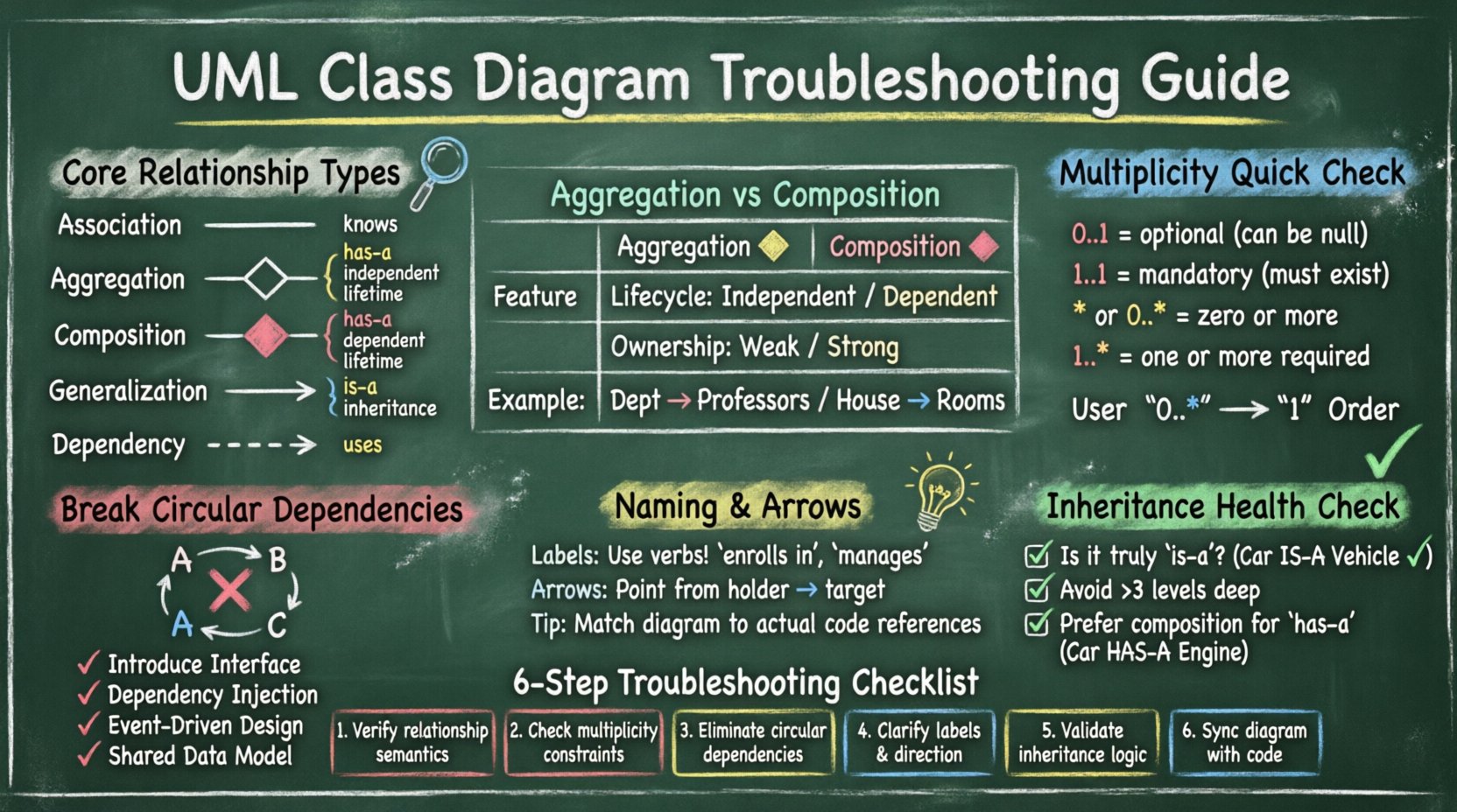
Before troubleshooting, one must understand the standard relationships defined in the UML specification. Confusion often arises when similar concepts are conflated. Below is a breakdown of the primary relationships used in class modeling.
- Association: A structural relationship that describes a connection between instances of classes. It is a general “knows” relationship.
- Aggregation: A specific type of association representing a “has-a” relationship where the lifetime of the part is independent of the whole.
- Composition: A stronger form of aggregation where the part cannot exist without the whole, implying a strict lifecycle dependency.
- Generalization: The “is-a” relationship, representing inheritance where a subclass inherits properties from a superclass.
- Dependency: A usage relationship where a change in the specification of one element affects the other, but without a structural link.
When troubleshooting, the first step is to verify if the relationship type matches the semantic meaning of the code logic. Many models fail because developers use Association lines for what should be Composition, or vice versa.
Comparison of Aggregation vs. Composition 🔄
One of the most frequent sources of error is distinguishing between aggregation and composition. Both imply a whole-part relationship, but the lifecycle management differs significantly.
| Feature | Aggregation | Composition |
|---|---|---|
| Lifecycle | Independent | Dependent |
| Ownership | Weak | Strong |
| Visual Symbol | Hollow Diamond | Filled Diamond |
| Example | A Department has Professors | A House has Rooms |
If your diagram shows a filled diamond but the code allows the part to exist after the whole is deleted, the diagram is incorrect. This mismatch creates a gap between the model and the implementation, which is a critical troubleshooting target.
Multiplicity and Cardinality Errors 🔢
Multiplicity defines how many instances of one class relate to one instance of another. Incorrect multiplicity is a common cause of logic bugs in the design phase. It dictates the constraints on the data model.
Common Multiplicity Mistakes
- Confusing 0..1 with 1..1: Using
1..1implies mandatory existence. Using0..1allows for null values. If the code handles nulls but the diagram does not, the model is misleading. - Ignoring Optional vs. Mandatory: Failing to specify whether a relationship is optional can lead to strict validation rules that are not enforced in the codebase.
- Incorrect Star Notation: Using
*(or0..*) implies zero or more. Sometimes1..*is required if at least one instance must exist.
Validating Multiplicity Logic
To troubleshoot multiplicity issues, walk through the lifecycle of the objects involved.
- Does the parent object require the child to exist upon creation?
- Can the child object exist without the parent?
- What happens to the child if the parent is destroyed?
If the answers do not align with the notation on the diagram, update the multiplicity markers. For example, a User can have zero Orders, but an Order must have exactly one User. This should be represented as 0..* on the User side and 1 on the Order side.
Resolving Circular Dependencies and Cycles 🚫
Circular dependencies occur when Class A depends on Class B, and Class B depends on Class A. While UML allows for cycles in association, they often indicate a design smell in the actual software architecture. These cycles create tight coupling, making the system hard to test and maintain.
Identifying Cycles
Visual inspection is the first step. Draw the path from Class A to Class B. If you can trace a line back to Class A without retracing your steps, a cycle exists. In large diagrams, these cycles are often hidden deep within the structure.
- Direct Cycles: A connects to B, B connects to A.
- Indirect Cycles: A connects to B, B connects to C, C connects to A.
Strategies to Break Cycles
When a cycle is identified as a problem, consider the following remediation strategies.
- Introduce an Interface: If A depends on B’s interface, and B depends on A’s interface, ensure the dependency is on the contract, not the concrete implementation.
- Dependency Injection: Shift the responsibility of creating objects. Instead of A creating B, have an external context provide B to A.
- Event-Driven Architecture: Use events to decouple the classes. A signals an event, B listens, but they do not hold direct references to each other.
- Shared Data Model: Create a third class that holds the data both A and B need, removing the need for them to reference each other directly.
Naming Conventions and Directionality 🏷️
A diagram is useless if its labels are ambiguous. Relationship names should describe the meaning of the connection, not just the class name. Directionality also plays a crucial role in understanding the flow of data and control.
Best Practices for Labels
- Use Verbs: An association between
StudentandCourseshould be labeled “enrolls in” or “takes” rather than just “Student”. - Pluralization: If the relationship is multiplicity-based (e.g., many to one), label the relationship from the perspective of the single side. For example,
Student->Courselabeled “enrolls in”. - Consistency: Ensure the terminology matches the domain language used by stakeholders. Avoid technical jargon in the diagram if the business users are the readers.
Arrow Direction and Readability
Association arrows indicate navigability. They show which object holds the reference to the other.
- Navigable: The arrow points from the holder to the target. If
Orderholds a reference toCustomer, the arrow points from Order to Customer. - Non-Navigable: No arrow or a line without arrowheads implies neither class holds a direct reference.
Troubleshooting involves checking if the arrows match the actual code. If the code shows customer.orders but the diagram shows an arrow from Order to Customer, the model is misleading regarding data access patterns.
Handling Generalization and Inheritance Issues 🌳
Generalization (inheritance) is powerful but often misused. Overuse leads to deep hierarchies that are fragile. Underuse leads to duplication. Troubleshooting involves evaluating the depth and breadth of the inheritance tree.
Signs of Poor Inheritance Design
- Deep Hierarchies: Classes nested more than three levels deep are often difficult to navigate and modify.
- Implementation vs. Interface: Confusing implementation inheritance with interface inheritance. In some languages, a class can only inherit from one parent, forcing the use of interfaces for multiple capabilities.
- The Diamond Problem: When a class inherits from two classes that both inherit from a common base, ambiguity can arise regarding method resolution.
Refactoring Inheritance Trees
If the diagram shows a complex inheritance structure, apply these checks.
- Is the relationship truly “is-a”? If a
Carhas anEngine, it is not an Engine. Do not use inheritance for “has-a” relationships. - Can the common behavior be extracted? If two subclasses share a method, move it to the superclass. If they share a method but with different logic, use polymorphism.
- Consider Composition: If inheritance is creating tight coupling, replace the relationship with composition. A
Carcan have anEngineobject rather than being anEngine.
Visual Clutter and Cognitive Load 🧠
A diagram that covers five pages is often a sign of poor organization. Visual clutter makes troubleshooting difficult because the eye cannot easily trace the flow. High cognitive load prevents stakeholders from understanding the system quickly.
Organizing Large Models
- Package Diagrams: Group related classes into packages. Use package diagrams to show the high-level structure without cluttering the class details.
- Sub-Diagrams: Split complex subsystems into their own class diagrams. Link them using package dependencies.
- Color Coding: Use visual cues to indicate status (e.g., red for deprecated, green for stable) or layer (e.g., presentation, business logic, data access).
Simplifying Associations
If a class has ten associations, it is likely doing too much. This is often a sign of a God Class. In troubleshooting, look for classes with excessive connections.
- Check Responsibility: Does this class handle UI, database, and business logic? If so, split it.
- Check Coupling: Is this class a hub for the entire system? Try to distribute the connections to helper classes.
Validation and Maintenance Best Practices ✅
Once the diagram is clean, it must be maintained. A diagram that is not updated with the code becomes a liability. It misleads new developers and slows down onboarding.
Keeping Diagrams in Sync
- Code Generation: Use tools that can generate diagrams from code to ensure accuracy.
- Code Annotation: Use comments in the code that reference the diagram sections.
- Review Process: Include diagram updates in the code review process. If the code changes, the diagram must change.
Common Maintenance Errors
| Error Type | Consequence | Fix |
|---|---|---|
| Stale Attributes | Developers miss new data fields | Sync diagram on every PR |
| Missing Methods | Confusion about available operations | Document public API only |
| Broken Links | Navigation fails in tools | Run validation scripts |
Advanced Troubleshooting Scenarios 🧩
Beyond the basics, there are specific scenarios that require deeper analysis. These often involve complex domain models or legacy system integrations.
Handling Legacy Code
When modeling existing systems, the code often does not match the original design. Do not try to force the code into a perfect diagram. Instead, document the reality.
- Annotate Deviations: Add notes explaining why the diagram differs from the code.
- Focus on Contracts: Document the interfaces and inputs/outputs rather than internal implementation details.
- Plan Migration: Use the diagram to plan the refactoring effort needed to align code and model.
Modeling Third-Party Integrations
External services often appear as black boxes in diagrams. Troubleshooting involves defining the boundaries clearly.
- Define Interfaces: Create classes that represent the external API.
- Mark as External: Use stereotypes or visual cues to indicate classes that are not owned by the team.
- Handle Errors: Document error handling paths in the relationships.
Summary of Troubleshooting Steps 📝
To ensure your UML Class Diagrams remain effective tools, follow this systematic approach when issues arise.
- Review Relationship Semantics: Verify that Association, Aggregation, and Composition match the lifecycle requirements.
- Check Multiplicity: Ensure cardinality constraints (0..1, 1..*) match the data validation rules.
- Eliminate Cycles: Break circular dependencies to reduce coupling and improve testability.
- Clarify Naming: Use verb-based labels and ensure directionality reflects data ownership.
- Validate Inheritance: Ensure “is-a” relationships are used correctly and hierarchies are not too deep.
- Maintain Synchronization: Update the model whenever the code changes to prevent drift.
By applying these principles, you transform your UML Class Diagrams from static drawings into dynamic, living documents that accurately guide development. The goal is not perfection, but clarity. A clear model reduces ambiguity, speeds up communication, and prevents costly errors during implementation.
Final Thoughts on Model Integrity 🛡️
The integrity of your design relies on the honesty of your model. If a relationship exists in code but not in the diagram, the diagram is incomplete. If a relationship exists in the diagram but not in code, the diagram is speculative. Striving for alignment between the two is the most effective way to troubleshoot complex relationships. Focus on the behavior and the data flow rather than just the visual layout. When the logic holds up, the visual representation will naturally become clear and useful for the entire team.
Remember that diagrams are communication tools, not just technical artifacts. If a stakeholder cannot understand the relationship between two classes within a few seconds, the design needs simplification. Simplification is not a sign of weakness; it is a sign of confidence in the design. Use the rules of UML to enforce discipline, but use your judgment to enforce clarity.
As you continue to build and refine your systems, keep this guide as a reference. Complex relationships are inevitable, but with the right troubleshooting strategies, they can be managed effectively. Your diagrams will serve as a reliable map for your team, guiding them through the architecture with confidence and precision.

