


Object-oriented design relies heavily on clear communication between architects, developers, and stakeholders. The Unified Modeling Language (UML) class diagram serves as the blueprint for this communication. However, a diagram that is visually cluttered or logically incorrect leads to implementation errors, refactoring debt, and confusion. Understanding the nuances of modeling is critical for maintaining system integrity. This guide details frequent pitfalls in class diagram creation and provides authoritative strategies to correct them.
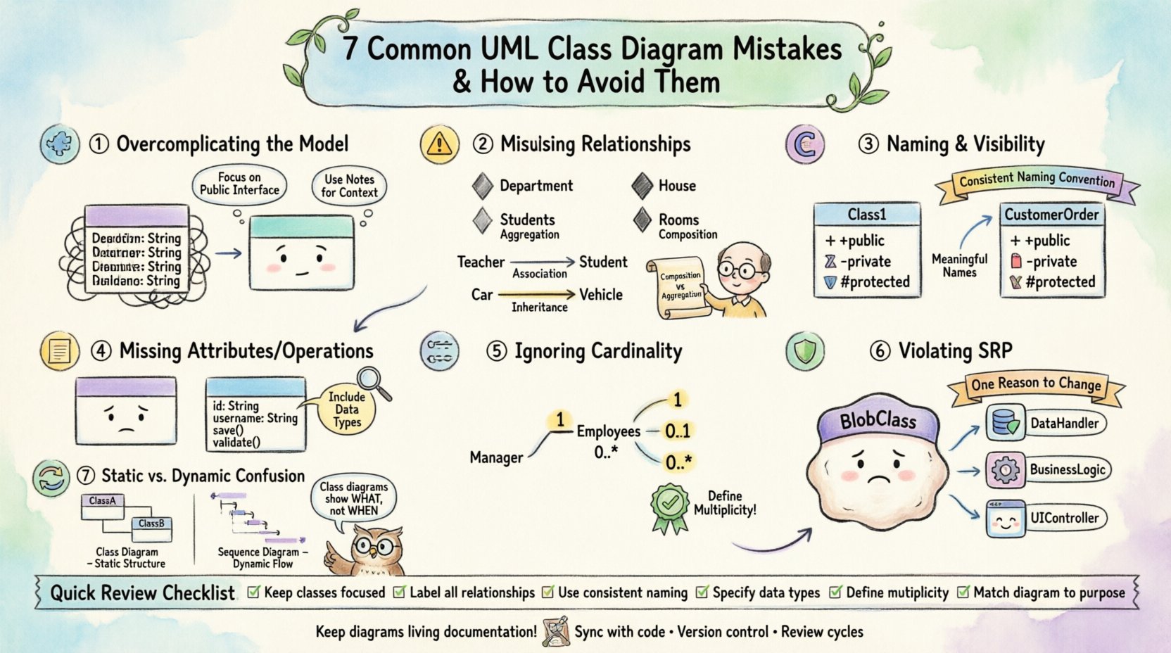
1. Overcomplicating the Model 🧩
One of the most prevalent errors is the attempt to model every conceivable detail in a single view. A class diagram should serve as a high-level overview of the system’s structure, not a line-by-line representation of every method. When designers include every getter, setter, and private variable, the diagram becomes unreadable. The cognitive load required to parse the information increases significantly, defeating the purpose of visualization.
- Focus on Public Interface: Prioritize methods and attributes that define the contract of the class. Internal implementation details often belong in code comments or sequence diagrams.
- Group Related Classes: If a subsystem is complex, consider creating separate diagrams for different domains rather than one massive diagram.
- Use Notes for Context: Instead of cluttering the class box, use UML notes to explain complex logic or business rules.
By simplifying the visual representation, you ensure that the diagram remains a useful reference throughout the development lifecycle. A clean diagram communicates intent better than a comprehensive one.
2. Misusing Relationships ⚠️
Relationships define how classes interact. Misinterpreting the strength and nature of these interactions leads to incorrect architectural boundaries. The distinction between association, aggregation, composition, and inheritance is often blurred.
Association vs. Aggregation vs. Composition
These three relationships describe ownership and lifecycle dependencies. Confusion here results in tight coupling where loose coupling is required.
- Association: A general structural relationship. One object references another, but neither owns the other.
- Aggregation: A “has-a” relationship where the contained objects can exist independently of the container.
- Composition: A strong “part-of” relationship. The part cannot exist without the whole.
Consider a library system. A Library has Books. If a book is removed from the library, does the book cease to exist? In composition, yes. In aggregation, no. Drawing a composition line where an aggregation is intended forces the code to manage the lifecycle of objects that should persist independently.
| Relationship Type | Lifecycle Dependency | Visual Symbol | Example |
|---|---|---|---|
| Association | None | Solid Line | Teacher teaches Student |
| Aggregation | Weak (Independent) | Hollow Diamond | Department has Students |
| Composition | Strong (Dependent) | Filled Diamond | House has Rooms |
| Inheritance | Is-a | Empty Triangle | Car is Vehicle |
Overuse of Inheritance
Deep inheritance hierarchies are a common source of rigidity. If a class inherits from five levels of parents, changes to the root class can cascade unpredictably. Designers should favor composition over inheritance where possible. This aligns with the principle that behavior should be delegated to helper objects rather than hardcoded into the class hierarchy.
3. Naming Conventions and Visibility 🔤
Naming is not merely aesthetic; it is semantic. Ambiguous names like Class1 or Manager without context provide no insight into the system. Furthermore, visibility modifiers (public, private, protected) are critical for defining the API surface.
- Consistency: Adopt a standard naming convention across the entire project. Use camelCase for attributes and PascalCase for classes, or vice versa, but remain consistent.
- Visibility Symbols: Use
+for public,-for private, and#for protected. These symbols are standard UML notation that conveys access levels instantly. - Contextual Names: Instead of
Order, considerCustomerOrderif the system handles multiple order types. Specificity reduces ambiguity for developers reading the code.
When visibility is ignored, developers may assume an attribute is accessible globally when it is meant to be encapsulated. This leads to fragile code where internal state is modified from external classes.
4. Missing Attributes and Operations 📝
A class diagram that lacks attributes or operations is often too abstract to be useful. While you should avoid over-specifying, omitting critical data fields leaves the reader guessing about the state of the object.
- Essential Attributes: Include fields that define the identity of the class. For a
Userclass,idandusernameare essential. - Operation Signatures: List key methods. You do not need every helper function, but the public API should be visible.
- Data Types: Specify types for attributes and return values for operations (e.g.,
int,String,Boolean). This clarifies validation requirements.
Without this information, the diagram fails to support code generation or detailed design reviews. It becomes a sketch rather than a specification.
5. Ignoring Cardinality and Multiplicity 🔢
Relationships without cardinality constraints are incomplete. Cardinality defines how many instances of one class relate to instances of another. Is it one-to-one? One-to-many? Many-to-many?
- Default Assumptions: Do not assume. Explicitly mark cardinality using notation such as
1,0..1,1..*, or0..*. - Database Implications: Cardinality directly impacts database schema design. A many-to-many relationship requires a junction table.
- Logic Validation: If a
ManagersupervisesEmployees, the cardinality should reflect that a manager might supervise zero employees (newly created) or many.
Missing multiplicity leads to runtime errors or database constraints that are not enforced until deployment. It is a low-cost fix during modeling that prevents high-cost fixes during development.
6. Violating Single Responsibility Principle 🛡️
The Single Responsibility Principle (SRP) states that a class should have one reason to change. In UML, this often manifests as classes that are too large or have too many responsibilities. A class handling data storage, business logic, and user interface rendering is a design smell.
- Granularity: Break large classes into smaller, focused units.
- Separation of Concerns: Ensure that data access logic is separated from business logic. This makes testing easier and changes less risky.
- Diagram Clarity: When SRP is followed, the class diagram becomes a map of distinct capabilities rather than a monolithic blob of functionality.
If a class in your diagram has three distinct sections of functionality that could logically exist elsewhere, split them. This improves modularity and maintainability.
7. Static vs. Dynamic Context Confusion 🔄
Class diagrams are static representations. They do not show the flow of execution. Confusing class diagrams with sequence or activity diagrams leads to expectations that are not met. A class diagram shows structure; it does not show behavior over time.
- State Representation: Do not attempt to draw state transitions in a class diagram. Use a State Machine Diagram instead.
- Flow Logic: Do not use class diagrams to show the order of operations. Use a Sequence Diagram.
- Interaction: Focus the class diagram on the relationships and attributes, leaving the “how” and “when” to behavioral diagrams.
Mixing these concerns confuses the reader. If they want to know how a transaction processes, a class diagram will not provide that answer. Keeping the static view static ensures it remains a reliable reference for the system architecture.
Review Checklist for Quality Assurance
Before finalizing a diagram, apply the following audit to ensure accuracy and clarity.
| Check Item | Criteria | Pass/Fail |
|---|---|---|
| Relationship Types | Are associations, aggregations, and compositions used correctly? | ☐ |
| Cardinality | Are multiplicities defined for all relationships? | ☐ |
| Visibility | Are +, -, and # symbols used correctly? | ☐ |
| Naming | Are names descriptive and consistent? | ☐ |
| Complexity | Is the diagram readable without zooming excessively? | ☐ |
| SRP Adherence | Do classes have a single, clear responsibility? | ☐ |
Ensuring Long-Term Maintainability 🛠️
A well-drawn UML class diagram is an asset that pays dividends over time. It serves as documentation when team members change and as a guide for onboarding new developers. However, diagrams must evolve. If the code changes and the diagram does not, the diagram becomes misleading. Treat the diagram as living documentation.
- Sync with Code: Whenever a class is refactored significantly, update the diagram.
- Version Control: Store diagram files in the same repository as the source code to ensure they are versioned together.
- Review Cycles: Include diagram reviews in code review processes. Ensure the design matches the implementation.
By maintaining fidelity between the model and the code, you preserve the integrity of the system architecture. This discipline prevents technical debt from accumulating in the design layer.

