Software architecture relies heavily on visual communication. Among the various tools available, the Unified Modeling Language (UML) Class Diagram stands out as a critical artifact for defining the static structure of a system. However, a diagram that is overly complex or poorly structured often becomes a burden rather than a benefit. It can obscure logic, confuse stakeholders, and lead to implementation errors. To ensure that these diagrams serve their purpose effectively, specific guidelines must be followed. This guide explores the essential strategies for constructing diagrams that are both clear to read and easy to maintain over time.
🏗️ Foundation: Scope and Granularity
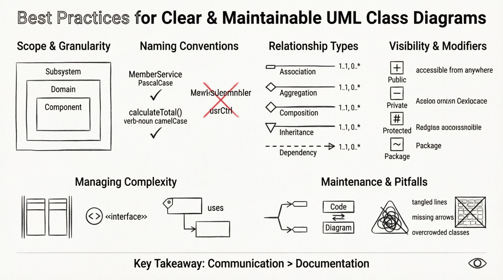
The first step in creating a useful diagram is determining the scope. A common mistake is attempting to model an entire application within a single view. This results in a cluttered mess where relationships are hard to trace. Instead, divide the system into logical boundaries. Consider the size of the class list; if a diagram exceeds the number of classes that can be comfortably viewed on a single screen without scrolling, it is likely too dense.
- Subsystem Level: Focus on the interaction between major modules rather than individual classes.
- Domain Level: Focus on the business entities and their direct relationships.
- Component Level: Drill down into specific functional areas when necessary.
Granularity also dictates the level of detail included. A high-level architectural diagram should omit method signatures and focus on class names and associations. Conversely, a detailed design diagram used by developers may require visibility modifiers and method lists. Distinguishing between these levels prevents information overload for different audiences.
📝 Naming Conventions and Semantics
Names are the primary vehicle for understanding in a diagram. If class names are ambiguous, the diagram loses its value. Adhering to strict naming conventions ensures consistency and reduces cognitive load. Names should reflect the domain concept rather than implementation details.
- Domain Driven: Use terms that stakeholders understand. Instead of
UserController, considerMemberServiceif it represents business logic. - CamelCase: Standardize on PascalCase for classes and camelCase for methods to maintain visual uniformity.
- No Abbreviations: Avoid acronyms unless they are universally recognized within the team.
- Verb-Noun Structure: For methods, use a verb-noun structure (e.g.,
CalculateTotal) to clearly indicate action and return.
Consistency in naming also extends to relationships. If an association is labeled, the label should describe the role from both sides. Avoid generic labels like Link or Ref. Instead, use manages, owns, or reports to.
🔗 Understanding Relationships and Associations
Relationships define how classes interact. Misusing these can lead to incorrect architectural decisions. The four primary relationship types must be applied correctly to reflect the lifecycle and dependency of the objects.
| Relationship | Symbol | Meaning | Cardinality |
|---|---|---|---|
| Association | Line | General connection | 1..1, 0..* |
| Aggregation | Open Diamond | Whole-Part (Part can exist independently) | 1..1, 0..* |
| Composition | Filled Diamond | Whole-Part (Part cannot exist independently) | 1..1, 0..* |
| Inheritance | Triangle Arrow | Generalization (Is-a relationship) | 1..1 |
| Dependency | Dashed Arrow | Usage (Temporary dependency) | 1..1 |
Aggregation vs. Composition
This distinction is often misunderstood. Aggregation implies a relationship where the child can exist without the parent. For example, a Department might have many Employees, but if the department is dissolved, the employees still exist. Composition is stronger. A House is composed of Rooms. If the house is destroyed, the rooms cease to exist in that context. Using the correct symbol clarifies ownership and lifecycle management.
Inheritance Hierarchy
Overusing inheritance leads to deep hierarchies that are brittle. Favor composition over inheritance when possible. If a class has a relationship that is not a strict “is-a” relationship, do not use inheritance. Keep hierarchies flat. Three levels of depth are often the maximum recommended for readability.
Dependencies
Dependencies indicate that a class uses another class temporarily, perhaps as a parameter in a method. These are the most common relationships but are also the most likely to be ignored. Marking them explicitly helps identify coupling points. High coupling suggests that changes in one class may ripple through many others.
👁️ Managing Visibility and Modifiers
Visibility modifiers control access to class members. In a diagram, showing these correctly helps developers understand encapsulation boundaries. While not every diagram needs to show every method, the public interface should be visible.
- Public (+): Accessible from any other class. This is the contract of the class.
- Private (-): Accessible only within the class. Internal state management.
- Protected (#): Accessible within the class and subclasses.
- Package (~/~): Accessible within the same package or namespace.
When creating diagrams for high-level design, showing private methods adds noise. However, for detailed design, hiding them can obscure logic. Strike a balance. If a class has twenty private methods, summarize them or show only the ones relevant to the current diagram’s context.
Static Members
Static members belong to the class itself rather than an instance. They are often underlined in diagrams. Use them sparingly for utility functions or constants. Excessive static usage can make unit testing difficult and introduce global state.
📐 Handling Complexity and Scale
As systems grow, diagrams grow. Managing this growth requires structural techniques to maintain clarity.
Partitioning
Partitioning divides a large diagram into smaller sections. You can use swimlanes or distinct boxes to group related classes. This helps users locate specific functionality quickly without scanning the entire canvas.
Interfaces
Interfaces define a contract that classes must implement. In diagrams, they are often represented as a stereotype or a specific shape (like a circle with a plus sign). Using interfaces reduces coupling. Instead of a class depending on a concrete implementation, it depends on an interface. This allows for flexibility and swapping implementations without changing the client code.
Package Dependencies
For very large systems, a single diagram is insufficient. Create a package diagram that shows dependencies between packages, and then create detailed class diagrams for each package. This hierarchical approach allows stakeholders to see the big picture without getting lost in the details.
Forward and Reverse Engineering
While manual creation offers control, reverse engineering from code ensures accuracy. However, relying solely on reverse engineering often results in cluttered diagrams that include everything. Manual refinement is essential to remove internal implementation details that are irrelevant to the architecture.
📝 Documentation and Annotations
Sometimes, a symbol or relationship is not enough to convey the full intent. Annotations and notes provide context that cannot be captured in the syntax of the diagram.
- Constraints: Use text to specify constraints like
{unique}or{must be positive}. - Business Rules: Add notes to explain complex logic that spans multiple classes.
- Comments: Use comments to explain why a certain design decision was made.
These notes should be concise. Long paragraphs belong in a separate document or wiki page. The diagram should point to the documentation, not contain it all.
🔄 Maintenance and Evolution
A diagram is a living document. Code changes, and the diagram must change with it. Outdated diagrams are worse than no diagrams at all because they mislead developers.
Version Control
Store diagram files in the same version control system as the source code. This ensures that diagram versions match code versions. When a class is added or removed, the diagram commit should be included in the same pull request.
Syncing with Code
Establish a workflow where the diagram is generated or updated during the build process or as part of the documentation pipeline. If manual updates are required, assign ownership. Designate a lead architect or senior developer responsible for reviewing diagram changes.
Refactoring the Diagram
Just as code is refactored, diagrams should be refactored. If you find yourself constantly drawing arrows that cross the entire canvas, the layout is likely flawed. Reorganize classes to minimize crossing lines. Group classes by their relationship density. This improves readability and makes the diagram easier to navigate.
⚠️ Common Pitfalls to Avoid
Even experienced practitioners fall into traps that reduce diagram quality. Recognizing these pitfalls early can save significant time.
| Pitfall | Impact | Mitigation |
|---|---|---|
| Over-Engineering | Diagram takes longer to write than code | Focus on the architecture, not every method |
| Hidden Dependencies | Unclear coupling | Explicitly mark all dependencies |
| Too Many Associations | Cluttered visual | Use navigation arrows to imply direction |
| Ignoring Cardinality | Incorrect data relationships | Always define minimum and maximum counts |
| Outdated Models | Confusion for new team members | Integrate diagram updates into CI/CD |
Visual Clutter
Too many lines crossing each other make the diagram unreadable. This is often a sign of tight coupling. If the diagram looks like a spiderweb, review the design. Consider breaking classes into smaller units or introducing intermediate interfaces to reduce direct connections.
Directionality
Association lines are often bidirectional. In reality, navigation usually flows in one direction. Use arrowheads to indicate the direction of navigation. If a class A knows about class B, but B does not know about A, draw a directed arrow. This clarifies the flow of control.
🔍 Review and Validation
Before finalizing a diagram, it should undergo a review process. This is not just about syntax but about logical correctness.
- Consistency Check: Do class names match the codebase?
- Completeness Check: Are all required entities present?
- Readability Check: Can a new developer understand the flow within five minutes?
Feedback from peers is invaluable. Sometimes a diagram that makes sense to the creator is confusing to others. Walkthroughs where you explain the diagram to a colleague can reveal ambiguities that were previously invisible.
🛠️ Integration with Development Workflow
Integrating diagramming into the daily workflow ensures that the documentation remains relevant. This means treating the diagram as code. It should be reviewed, tested for accuracy, and committed.
When starting a new feature, update the diagram to reflect the new classes or changes. This practice, known as “modeling as you code,” keeps the visual representation in sync with the implementation. It prevents the drift that occurs when documentation is updated months after the feature is released.
Furthermore, use the diagram during the design phase to validate requirements. If the relationships do not make sense in the diagram, they will not make sense in the code. Fixing issues at this stage is significantly cheaper than fixing them after implementation.
🌐 Accessibility and Collaboration
Diagrams are often shared with non-technical stakeholders. Ensure that the diagram is accessible to them. Avoid overly technical jargon where possible. Use colors sparingly to highlight important elements, but ensure the diagram remains legible in black and white if printed.
Collaboration tools allow multiple people to work on a diagram simultaneously. This can speed up the design process, but it requires strict version control to avoid conflicts. Ensure that changes are reviewed before being merged into the main branch.
📊 Summary of Key Takeaways
To create effective UML Class Diagrams, focus on clarity and maintainability. Start with a clear scope and use consistent naming conventions. Apply relationships correctly to reflect lifecycle and dependency. Manage complexity through partitioning and interfaces. Document annotations where necessary but keep them concise. Maintain the diagrams alongside the code to prevent obsolescence. Avoid common pitfalls like over-engineering and hidden dependencies.
By following these practices, the diagrams become a valuable asset for the entire team. They serve as a single source of truth, facilitate communication, and reduce the risk of architectural drift. The effort invested in creating a well-structured diagram pays dividends in reduced maintenance costs and clearer understanding of the system.
Remember that the goal is communication, not just documentation. A diagram that is understood by the team is a successful diagram. Prioritize the needs of the reader over the desire to show every detail. Keep it simple, keep it accurate, and keep it updated.

