


Software engineering relies heavily on visualization to communicate complex systems. Among the various modeling tools available, the Unified Modeling Language (UML) stands as the industry standard. Specifically, the UML class diagram serves as a critical blueprint for object-oriented design. It captures the static structure of a system, defining how data and behavior are organized. This guide explores the mechanics, syntax, and strategic application of class diagrams without referencing specific software tools.
Understanding these diagrams is essential for architects, developers, and stakeholders. They provide a shared language that reduces ambiguity during the development lifecycle. By mapping out classes, attributes, and relationships before writing code, teams can identify potential design flaws early. This document serves as a comprehensive reference for mastering the visual representation of software architecture.
📐 What Is a UML Class Diagram?
A UML class diagram is a static structure diagram that describes the structure of a system by showing the system’s classes, their attributes, operations, and the relationships among objects. Unlike sequence diagrams that focus on dynamic behavior over time, class diagrams focus on the noun-based structure of the domain.
Key characteristics include:
- Static View: It represents the system at a specific point in time, not a sequence of events.
- Object-Oriented Focus: It is designed specifically for object-oriented languages like Java, C++, and Python.
- Abstraction: It allows teams to model abstract concepts alongside concrete implementation details.
- Documentation: It acts as living documentation that evolves with the codebase.
When designing a system, these diagrams act as the schema for the database and the class hierarchy in the code. They ensure that the logical design aligns with the physical implementation.
🧱 Anatomy of a Class
At the center of every class diagram is the class itself. In UML notation, a class is represented by a rectangle divided into three compartments. Each compartment serves a distinct purpose in defining the entity’s identity and behavior.
1. The Class Name Compartment
The top section contains the name of the class. Naming conventions are critical here. Names should be nouns and capitalized (PascalCase). For example, Customer, Order, or PaymentProcessor. This section identifies the type of object being modeled.
2. The Attributes Compartment
The middle section lists the properties or data members of the class. These represent the state of the object. Each attribute typically includes:
- Visibility: A symbol indicating access level (+, -, #, ~).
- Name: The variable name (camelCase).
- Type: The data type (e.g., String, Integer, Boolean).
- Default Value: An optional initial value (e.g.,
active = true).
3. The Operations Compartment
The bottom section defines the methods or behaviors available to the class. Similar to attributes, operations include visibility, name, parameters, and return types. For instance, + calculateTotal(): Decimal.
Here is a visual representation of a standard class structure:
| Compartment | Content | Example |
|---|---|---|
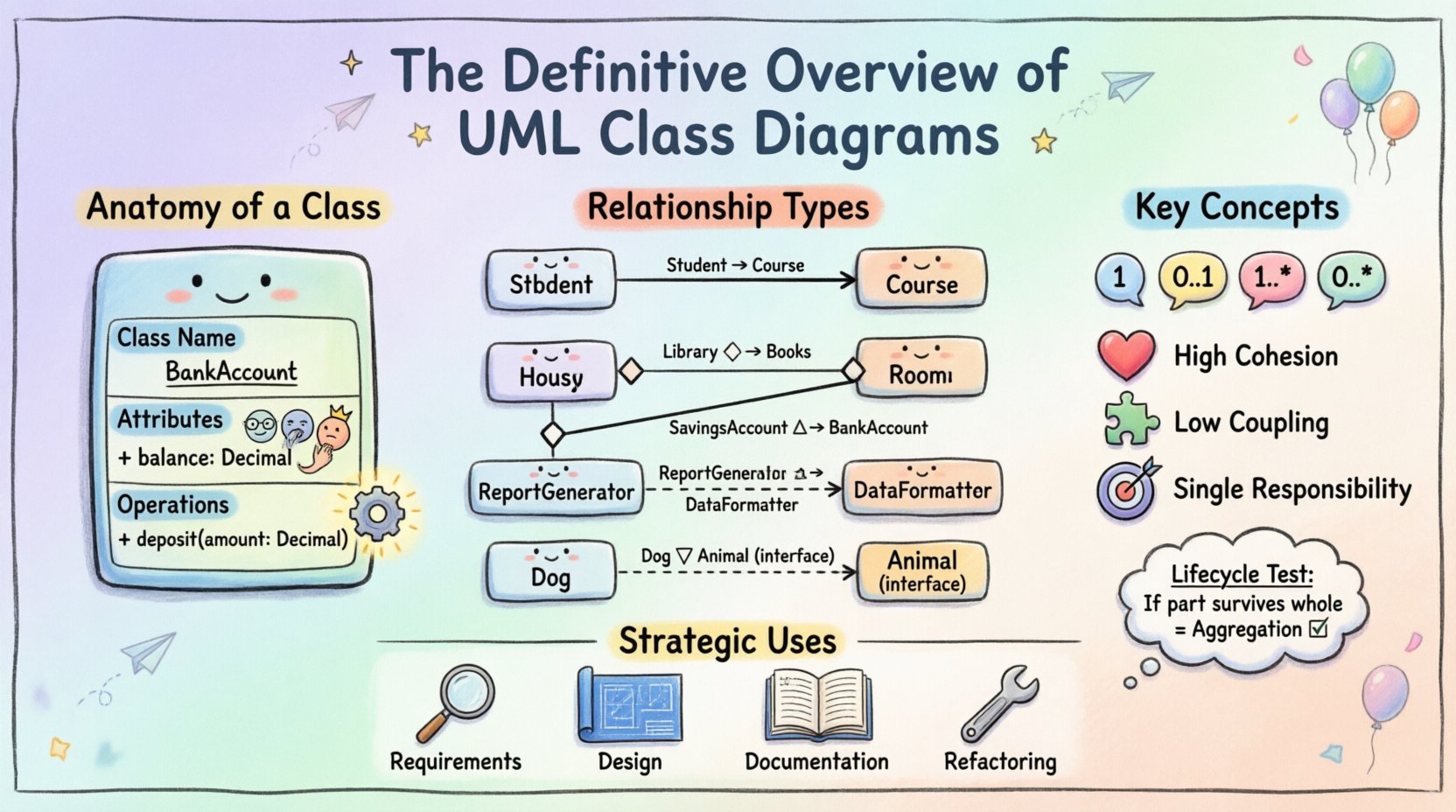
| Name | Class Identifier | BankAccount |
| Attributes | Data Properties | + balance: Decimal |
| Operations | Methods/Behaviors | + deposit(amount: Decimal) |
🔗 Understanding Relationships
Classes rarely exist in isolation. They interact with one another to form a cohesive system. UML defines several types of relationships to describe these interactions. Understanding the nuances between them is vital for accurate modeling.
1. Association
An association represents a structural relationship between two classes. It indicates that objects of one class are connected to objects of another. This is the most generic relationship.
- Direction: Can be unidirectional (arrow) or bidirectional (line).
- Role Name: Describes the purpose of the link from one class’s perspective.
- Multiplicity: Defines how many instances participate in the relationship.
For example, a Student enrolls in a Course. The association implies that a student object holds a reference to a course object.
2. Aggregation
Aggregation is a specialized form of association representing a whole-part relationship where the part can exist independently of the whole. It is often described as a “has-a” relationship.
- Notation: A hollow diamond at the “whole” end of the line.
- Lifecycle: If the whole is destroyed, the part continues to exist.
Consider a Department and Professor. If the department is dissolved, the professor still exists as an individual. The professor is aggregated by the department, but does not belong exclusively to it.
3. Composition
Composition is a stronger form of aggregation. It implies a strict ownership and lifecycle dependency. The part cannot exist without the whole.
- Notation: A filled diamond at the “whole” end.
- Lifecycle: If the whole is destroyed, the parts are destroyed as well.
- Exclusivity: A part typically belongs to only one whole.
A classic example is a House and Room. If the house is demolished, the rooms cease to exist in that context. The rooms are composed of the house.
4. Generalization (Inheritance)
Generalization represents an inheritance hierarchy. It allows a subclass to inherit the attributes and operations of a superclass. This promotes code reuse and polymorphism.
- Notation: A solid line with a hollow triangle arrow pointing to the superclass.
- Is-A Relationship: The subclass is a type of the superclass.
For instance, a SavingsAccount is a type of BankAccount. The savings account inherits the balance and name properties but adds interest calculation logic.
5. Dependency
Dependency indicates a usage relationship where a change in the specification of the independent element may cause a change in the dependent element. It is a temporary relationship.
- Notation: A dashed line with an open arrow.
- Usage: Often occurs when one class uses another as a parameter in a method.
If a ReportGenerator class uses a DataFormatter class to format output, the generator depends on the formatter. If the formatter changes, the generator might need to adapt.
6. Realization (Interface Implementation)
Realization connects a class to an interface. It indicates that the class guarantees to implement the operations defined by the interface.
- Notation: A dashed line with a hollow triangle arrow.
- Contract: The class adheres to the interface contract.
If an Animal interface defines makeSound(), a Dog class realizing this interface must implement the makeSound() method.
📏 Multiplicity and Cardinality
Multiplicity defines the number of instances of one class that can relate to instances of another class. It is placed at the ends of association lines. Accurate multiplicity prevents logical errors in the design.
Common multiplicity notations include:
- 1: Exactly one instance.
- 0..1: Zero or one instance (optional).
- 1..*: One or more instances.
- 0..*: Zero or more instances.
- 1..3: Between one and three instances.
Understanding these constraints helps in database schema design and validation logic. For example, an Order must contain at least one Item (1..*), but a Customer might have zero Orders (0..*). These rules are critical for maintaining data integrity.
🛠️ Design Principles and Best Practices
Creating a class diagram is not just about drawing boxes and lines. It requires adherence to sound software engineering principles. Poorly designed diagrams lead to poorly designed systems.
1. High Cohesion
Keep related functionality within the same class. If a class handles database connections, email sending, and UI rendering, it violates cohesion. Split these concerns into separate classes. High cohesion makes classes easier to understand and maintain.
2. Low Coupling
Minimize dependencies between classes. If Class A changes, Class B should not necessarily break. Use interfaces or dependency injection to reduce tight coupling. This makes the system more flexible and testable.
3. Single Responsibility Principle
Every class should have one reason to change. This aligns with cohesion. A User class should manage user data, not handle login authentication logic. Separation of concerns improves clarity.
4. Naming Conventions
Consistent naming reduces cognitive load. Use domain language. Instead of Entity1, use Invoice. Avoid abbreviations unless they are industry standard. Names should be self-explanatory.
5. Abstraction Levels
Do not model every single field in a massive diagram. Create different views for different audiences. A high-level architectural diagram should show major components, while a detailed design diagram should show specific attributes. Context determines granularity.
🚫 Common Pitfalls to Avoid
Even experienced designers make mistakes when modeling systems. Being aware of common errors helps in refining the model.
- Over-Modeling: Trying to map every single attribute leads to clutter. Focus on the domain model first.
- Confusing Aggregation and Composition: This is the most common error. Remember the lifecycle test. If the part survives the whole, it is aggregation. If not, it is composition.
- Ignoring Visibility: Public, private, and protected modifiers affect how the class interacts with the rest of the system. Omitting them hides critical constraints.
- Circular Dependencies: If Class A depends on Class B, and Class B depends on Class A, it creates a cycle that complicates loading and execution. Break cycles with interfaces or abstract factories.
- Ignoring Static Members: Static methods and attributes belong to the class, not instances. They should be clearly marked (often underlined in diagrams) to distinguish them from instance members.
📈 Strategic Application
Class diagrams are most effective when used at specific stages of the software development lifecycle.
1. Requirements Analysis
During the analysis phase, diagrams help stakeholders visualize the domain. They confirm that the team understands the business rules regarding how entities relate. This prevents costly rework later.
2. System Design
Architects use these diagrams to plan the structure. They decide on inheritance hierarchies and interface contracts. This phase sets the foundation for the code structure.
3. Documentation and Onboarding
For new team members, class diagrams provide a map of the codebase. They explain how the system is organized without requiring the reader to parse thousands of lines of code.
4. Refactoring
When legacy code becomes difficult to maintain, reverse-engineering class diagrams can reveal the current state of the system. This allows teams to plan a refactoring strategy to improve structure.
📊 Comparing Relationship Types
To clarify the distinctions between relationship types, consider the following comparison table:
| Relationship | Notation | Strength | Lifecycle | Example |
|---|---|---|---|---|
| Association | Solid Line | Weak | Independent | Teacher teaches Student |
| Aggregation | Hollow Diamond | Medium | Independent | Library has Books |
| Composition | Filled Diamond | Strong | Dependent | Car has Engine |
| Generalization | Hollow Triangle | Inheritance | Shared | Circle is Shape |
Understanding these distinctions ensures that the model accurately reflects the business reality. Misinterpreting a relationship can lead to incorrect database foreign keys or flawed object references in code.
🔍 Advanced Concepts
Beyond basic structures, there are advanced concepts that refine the model.
Abstract Classes
An abstract class cannot be instantiated directly. It serves as a template for subclasses. In the diagram, the name is often italicized. This is useful for defining common behavior that must be specialized by children classes.
Interfaces
Interfaces define a contract without implementation. They are crucial for decoupling systems. A class can realize multiple interfaces, allowing for flexible composition. Interfaces are often depicted with a <
Static Attributes
Static attributes are shared across all instances of a class. They are often used for counters or configuration settings. In diagrams, they are underlined to distinguish them from instance variables.
📝 Final Thoughts
The UML class diagram remains a cornerstone of object-oriented design. It bridges the gap between abstract requirements and concrete code. By mastering the elements, relationships, and best practices outlined in this guide, teams can construct robust, maintainable systems. The key lies in clarity and precision. Use the diagram to communicate, not just to document. Ensure that every box and line serves a purpose in the overall architecture.
As systems grow in complexity, the need for clear structural representation increases. Regularly reviewing and updating these diagrams keeps the team aligned with the evolving business needs. Whether designing a small utility or a large enterprise platform, the principles of class modeling provide the necessary structure for success.

