


In the landscape of system architecture, clarity is the currency of success. When architects design complex software systems, they rely on visual abstractions to communicate intent. Among these abstractions, the component diagram stands out as a critical tool for defining the physical or logical modular structure of a system. However, a component diagram without well-defined interfaces is merely a map without roads. 🗺️
Interfaces serve as the contract between components. They dictate how information flows, how services are requested, and how systems interact without knowing the internal secrets of one another. Understanding the nuance of these contracts is essential for building maintainable, scalable, and robust software. This guide explores the mechanics of interfaces within component diagrams, focusing on design principles that ensure longevity and stability.
🧱 Understanding the Core Concepts
Before diving into the specifics of diagramming, it is vital to distinguish between the container and the connection. A component represents a modular part of a system that encapsulates implementation. It is the black box. An interface, conversely, is the surface of that box. It is what is exposed to the outside world.
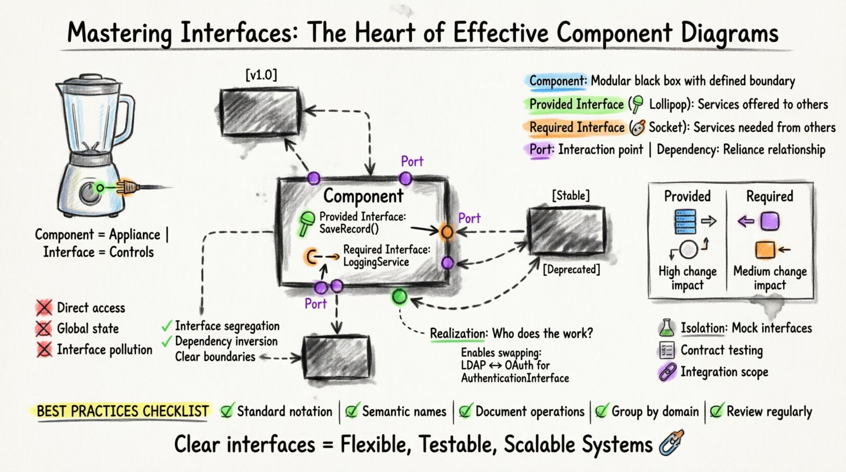
Think of a component as a kitchen appliance. The appliance itself (the component) does the work. The buttons and plugs (the interfaces) allow you to interact with it without needing to know how the internal circuitry works. In software architecture, this separation allows teams to work independently. If the internal logic of a payment processing component changes, the application using it does not break, provided the interface remains consistent.
🔑 Key Definitions
- Component: A modular part of a system that encapsulates code and data. It has a defined boundary and exposes functionality.
- Interface: A set of operations that a component provides or requires. It defines the contract of interaction.
- Port: A designated point of interaction on a component where interfaces are connected. Think of this as the physical socket on the appliance.
- Dependency: A relationship indicating that one component relies on another to function. This is often mediated by interfaces.
🔄 Provided vs. Required Interfaces
Interfaces are not monolithic; they have distinct directions. Recognizing the difference between what a component does and what a component needs is the first step in effective diagramming.
1. Provided Interfaces (The Lollipop)
These are the services a component offers to others. In a diagram, this is often depicted as a circle or a ball attached to a port. It signifies that the component is ready to serve data or execute logic upon request. 🎯
- Visibility: Public. Anyone with access to the port can invoke these operations.
- Responsibility: The component guarantees that these operations will behave according to the specification.
- Example: A
DatabaseServiceproviding aSaveRecord()operation.
2. Required Interfaces (The Socket)
These are the services a component needs from others to fulfill its own purpose. In diagrams, this is often shown as a half-circle or a socket. It represents a dependency. 🔌
- Visibility: Internal. The component declares it needs this, but does not implement it.
- Responsibility: The component expects another component to fulfill this role. If it is not found, the component cannot function.
- Example: The same
DatabaseServicemight require aLoggingServiceto record errors.
📊 Comparison of Interface Types
| Feature | Provided Interface | Required Interface |
|---|---|---|
| Role | Server / Provider | Client / Consumer |
| Dependency Direction | Outward (Offering) | Inward (Needing) |
| Diagram Symbol | Circle (Lollipop) | Socket (Half-Circle) |
| Change Impact | High (Breaking changes affect consumers) | Medium (Breaking changes affect the component itself) |
| Implementation | Code exists within the component | Code exists in a connected component |
🔗 The Role of Realization Relationships
One of the most powerful features in component diagramming is the realization relationship. This connects an interface to a component that implements it. It answers the question: “Who is actually doing the work?”
Without realization, a diagram is just a wishlist of requirements. Realization brings it to life. It signifies that the component contains the logic necessary to satisfy the interface contract. This is crucial for understanding the flow of control and data.
Why Realization Matters
- Traceability: It allows you to trace a requirement (interface) back to the implementation (component).
- Verification: It helps verify that every required service has a provider.
- Flexibility: It allows multiple components to realize the same interface. This enables swapping implementations without changing the system architecture.
For instance, a AuthenticationInterface might be realized by a LDAPComponent or a OAuthComponent. Both components satisfy the same interface, allowing the system to switch authentication methods without altering the login flow logic.
📉 Managing Coupling and Cohesion
The primary goal of defining interfaces clearly is to control coupling. Coupling refers to the degree of interdependence between software modules. High coupling makes systems brittle. Low coupling makes them flexible.
High Coupling Anti-Patterns
- Direct Implementation Access: If Component A calls internal methods of Component B directly, rather than through an interface, they are tightly coupled. Changing B breaks A.
- Global State: Relying on global variables or shared memory instead of passing data through interfaces creates hidden dependencies.
- Interface Pollution: Creating an interface that exposes too many operations forces the consumer to depend on features it does not use, increasing the surface area for errors.
Strategies for Low Coupling
- Interface Segregation: Keep interfaces small and focused. A component should only depend on the specific operations it needs.
- Dependency Inversion: Depend upon abstractions (interfaces), not concretions (specific classes or components).
- Boundary Definition: Clearly mark what is inside the component and what is outside. Interfaces define this boundary.
🛠️ Designing for Versioning and Evolution
Software is not static. Requirements change, bugs are fixed, and features are added. When interfaces evolve, they can break existing systems. Managing this evolution is a critical aspect of component design.
Versioning Strategies
- Version Numbers: Explicitly version the interface (e.g.,
Interface v1.0,Interface v1.1). This allows consumers to specify which version they support. - Backward Compatibility: When updating an interface, avoid removing existing operations. Instead, add new ones. If an operation must be removed, mark it as deprecated first.
- New Interface: If a change is too drastic, create a new interface (e.g.,
Interface v2) and migrate components gradually.
In a component diagram, it is helpful to annotate interfaces with version numbers or status tags (e.g., [Stable], [Experimental]). This visual cue helps developers understand the maturity of the contract.
🧪 Testing and Validation
Interfaces facilitate testing by allowing isolation. Because components communicate through defined contracts, you can mock or stub these interfaces during unit testing.
Benefits for Testing
- Isolation: You can test Component A without needing Component B to be fully running. You simply provide a mock implementation of the required interface.
- Contract Testing: Automated tests can verify that the implementation matches the interface specification. If the component changes behavior, the test fails, alerting the team.
- Integration Testing: Component diagrams help define the scope of integration tests. You know exactly which ports need to be connected to validate the system flow.
⚠️ Common Design Pitfalls
Even experienced architects can fall into traps when designing component diagrams. Awareness of these pitfalls prevents technical debt accumulation.
1. The God Interface
A single interface that requires knowledge of the entire system is a sign of poor design. It violates the principle of separation of concerns. Instead, break this down into smaller, domain-specific interfaces.
2. Circular Dependencies
If Component A requires Interface X, and Component B provides Interface X, but Component B also requires an interface provided by Component A, you have a cycle. This often leads to initialization errors and difficulty in deployment. Component diagrams should ideally be acyclic regarding dependencies.
3. Ignoring Asynchronous Interfaces
Not all communication is synchronous. Some interfaces trigger events rather than waiting for a return value. Failing to distinguish between synchronous calls and asynchronous events in a diagram can confuse the implementation team regarding error handling and timeouts.
✅ Best Practices Checklist
To ensure your component diagrams remain effective over time, adhere to the following standards.
- ✅ Use Standard Notation: Stick to established conventions for ports and interfaces to ensure readability across the team.
- ✅ Keep Names Semantic: Use names that describe the service, not the class. Use
PaymentProcessorinstead ofPaymentProcessorImpl. - ✅ Document Operations: Briefly describe the purpose of key operations within the interface definition.
- ✅ Group Related Interfaces: Use packages or folders to group interfaces by domain (e.g.,
SecurityInterfaces,DataInterfaces). - ✅ Review Regularly: Diagrams rot. Schedule regular reviews to ensure the diagram matches the current codebase.
🚀 Scaling Interface Design
As systems grow from monoliths to distributed architectures, the role of interfaces expands. In microservices, for example, interfaces often become network contracts (like REST endpoints or gRPC services).
From In-Memory to Network
In a monolithic application, component interactions are usually direct method calls. In a distributed system, these become network calls. The component diagram remains valid, but the physical realization changes.
- Latency: Network calls introduce latency. Interface design should account for batching or asynchronous patterns.
- Fault Tolerance: Network calls fail. Interfaces must define how failures are communicated (timeouts, retry policies).
- Data Serialization: The interface definition often dictates how data is serialized (JSON, Protobuf, XML).
📝 Documentation and Maintenance
A diagram is useless if it is not maintained. The most effective component diagrams are living documents that evolve with the code.
Integration with Code
Some frameworks allow you to generate diagrams directly from code annotations. While this ensures accuracy, it can sometimes produce cluttered diagrams. A hybrid approach is often best: use code to generate the skeleton, but manually refine the high-level architecture for clarity.
Change Management
When a component is modified, the interface diagram should be updated as part of the pull request review process. This ensures that the visual documentation always reflects the source of truth. Automated tools can flag discrepancies between the code and the diagram.
🌐 The Impact on System Health
Investing time in precise interface definitions yields long-term dividends. Systems built with clear boundaries are easier to onboard new developers to. They are easier to refactor. They are easier to scale.
When every component speaks a clear language, the system as a whole becomes resilient. The interfaces act as shock absorbers, isolating changes and preventing ripple effects. This stability is not accidental; it is the result of deliberate design choices made at the component level.
By focusing on the heart of the diagram—the interfaces—you ensure that the structure remains sound even as the internal organs change. This is the essence of effective architectural design.
🔍 Summary of Key Takeaways
- Interfaces define the contract of interaction, separating implementation from usage.
- Distinguish clearly between Provided (offering) and Required (needing) interfaces.
- Use realization relationships to connect components to their contracts.
- Minimize coupling to increase flexibility and reduce risk.
- Plan for versioning to allow for evolution without breaking consumers.
- Maintain diagrams as part of the development lifecycle to prevent drift.
Effective component diagrams are not just drawings; they are blueprints for collaboration. They tell the story of how the system works without getting bogged down in the minutiae of every line of code. By prioritizing interfaces, you build a foundation that supports growth, change, and innovation.

