


Component modeling serves as the backbone of structured software architecture. It allows developers and architects to visualize how different parts of a system interact, ensuring maintainability and scalability. While many beginners stop at drawing simple boxes and lines, true mastery involves understanding the nuanced relationships between interfaces, ports, and dependencies. This guide explores the deeper layers of component diagrams, providing a clear path from basic shapes to robust architectural blueprints.
When we discuss component modeling, we are not just talking about drawing shapes. We are defining the contract of functionality within a system. A component represents a modular, deployable unit that encapsulates implementation details. By focusing on advanced concepts, you ensure that your diagrams communicate precise information to stakeholders, developers, and maintenance teams alike.
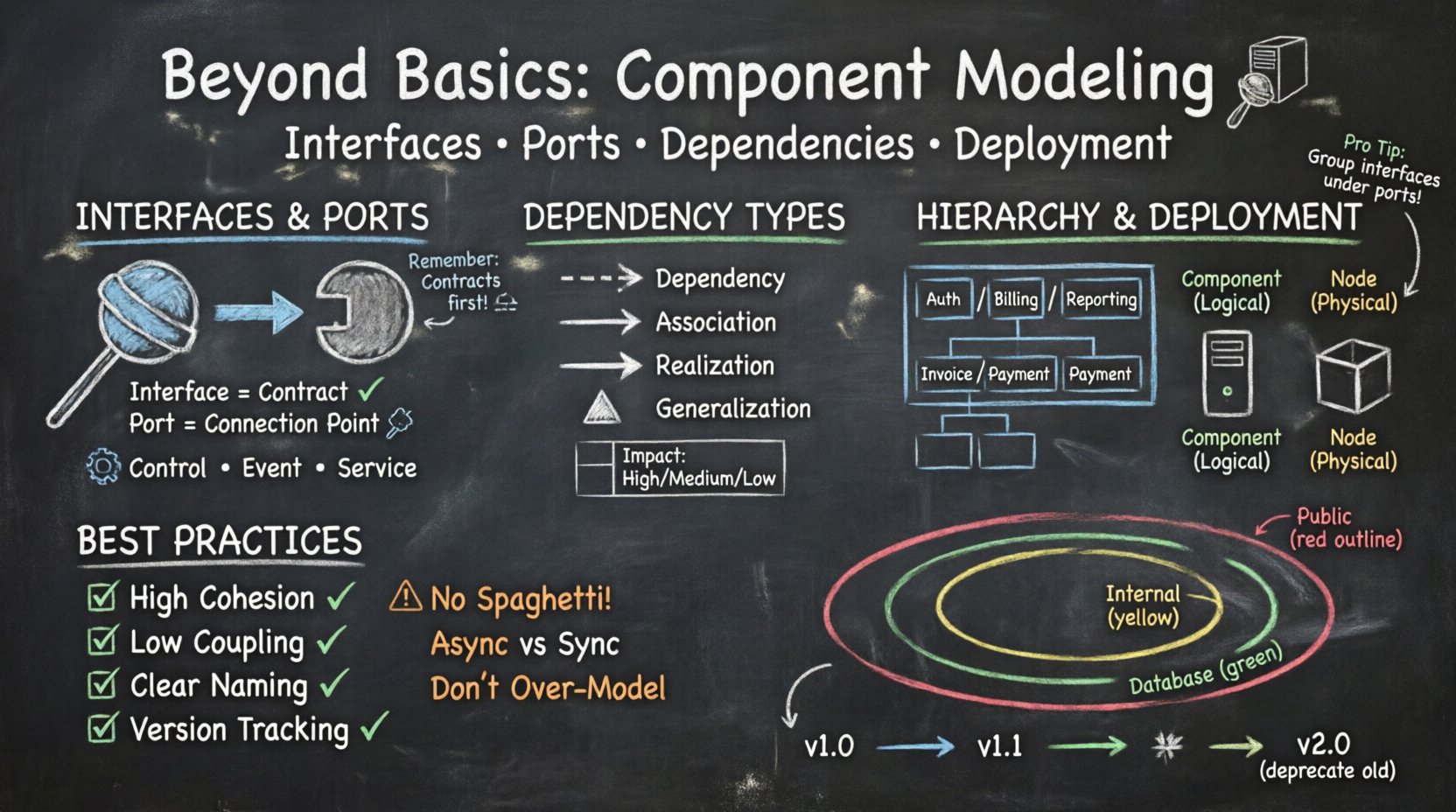
🔌 Understanding Interfaces and Ports
One of the most critical distinctions in advanced component modeling is the separation between an interface and a port. Confusing these two often leads to diagrams that are ambiguous or difficult to implement correctly.
Interfaces: The Contract
An interface defines a set of operations that a component provides or requires. It is purely functional. It answers the question: “What can this component do?” or “What does this component need to function?”
- Provided Interfaces: These are services that the component offers to the outside world. They are often depicted as a “lollipop” symbol attached to the component.
- Required Interfaces: These are services the component depends on. They are often depicted as a “socket” symbol attached to the component.
When designing a system, always ensure that every interaction point is defined by an interface. This abstraction allows the internal implementation to change without affecting external dependencies, provided the interface contract remains consistent.
Ports: The Connection Points
A port is a physical or logical point of interaction on a component. It acts as a container for interfaces. Think of a port as a physical socket on a wall, and the interface as the electrical standard (voltage, frequency) that the plug must match.
In advanced modeling, ports add granularity. A single component might have multiple ports to handle different types of traffic or protocols.
- Control Ports: Handle data flow or commands.
- Event Ports: Handle asynchronous events or notifications.
- Service Ports: Handle specific functional requests.
Using ports allows for a cleaner diagram. Instead of connecting every interface directly to every other component, you can group interfaces under a specific port. This reduces visual clutter and clarifies the architecture.
🔗 Dependency Management and Relationships
Relationships between components define the structure of the system. In basic modeling, a simple arrow might suffice. In advanced modeling, the type of arrow and its label carries significant semantic weight.
Types of Dependencies
Understanding the specific type of dependency helps in assessing risk and complexity. Not all connections are created equal.
- Dependency: A usage relationship. One component needs another to function. If the supplier changes, the client may break.
- Association: A structural relationship. Components are linked, often implying a “has-a” relationship.
- Realization: The component implements an interface. This is crucial for showing how a component fulfills a contract.
- Generalization: Inheritance-like behavior where one component is a specialized version of another.
Directionality and Multiplicity
Arrows should always point from the client to the supplier. This indicates the flow of dependency. Multiplicity (e.g., 1 to many) should be noted where relevant to understand how many instances might interact.
| Relationship Type | Symbol | Meaning | Impact on Change |
|---|---|---|---|
| Dependency | Dashed Arrow | Usage | High (Supplier change affects client) |
| Association | Solid Line | Connection | Medium (Structure change affects both) |
| Realization | Open Arrow | Implementation | Low (Contract is stable) |
| Generalization | Triangle Arrow | Inheritance | Medium (Hierarchy change affects children) |
📦 Hierarchical Refinement and Abstraction
A component diagram should not be a flat list of boxes. It should reflect the hierarchy of your system. Advanced modeling utilizes refinement to show how high-level components break down into lower-level implementations.
Composite Components
A composite component is a component that contains other components. This allows you to model complex subsystems without cluttering the high-level view.
- Top-Level View: Shows the major subsystems (e.g., Authentication, Billing, Reporting).
- Sub-Level View: Drill down into “Billing” to show specific modules like “Invoice Generator” and “Payment Processor”.
This technique supports the concept of abstraction. A stakeholder looking at the top level does not need to know the internal details of the billing engine, but the development team does.
Refinement Cycles
Refinement is not a one-time event. As the system evolves, components may be split or merged. Your diagrams should track these changes.
- Splitting: A large component becomes two smaller ones to reduce coupling.
- Merging: Two related components combine to improve cohesion.
🚀 Deployment and Physical Mapping
While component diagrams focus on logical structure, they often need to relate to physical deployment. Understanding how components map to nodes or devices is essential for infrastructure planning.
Component vs. Node
Components are logical units. Nodes are physical or virtual execution environments (servers, containers, devices). A single component might be deployed on multiple nodes, or a single node might host multiple components.
| Aspect | Component | Node |
|---|---|---|
| Nature | Logical / Functional | Physical / Runtime |
| Scope | Software Architecture | Infrastructure Architecture |
| Change Frequency | Low (Design time) | High (Ops time) |
Mapping Strategies
When linking components to deployment environments, consider the following strategies:
- One-to-One: A dedicated server for a specific component. Good for isolation.
- Many-to-One: Multiple components on a single server. Good for resource efficiency.
- Replication: The same component deployed on multiple nodes for high availability.
Clear mapping helps DevOps teams understand where to deploy artifacts and how to configure load balancers.
🛠️ Best Practices for Maintainability
A diagram that is hard to read is a diagram that will be ignored. Maintaining component models requires discipline and adherence to standards.
Coupling and Cohesion
The golden rule of software design applies to diagrams as well. You want high cohesion within components and low coupling between them.
- High Cohesion: A component should do one thing well. If a component handles logging, authentication, and database access, it is too complex.
- Low Coupling: Components should depend on interfaces, not concrete implementations. This allows you to swap out parts of the system without breaking others.
Naming Conventions
Consistent naming prevents confusion. Avoid generic names like “Component1” or “ModuleA”.
- Use verb-noun pairs for interfaces (e.g., “ProcessOrder”, “ValidateUser”).
- Use noun phrases for components (e.g., “OrderService”, “UserManager”).
- Prefix components based on their layer (e.g., “UI_”, “Logic_”, “Data_”).
Documentation Integration
Diagrams should not exist in isolation. They must be supported by textual descriptions.
- Preconditions: What must be true before this component runs?
- Postconditions: What is the state of the system after this component runs?
- Constraints: Any performance or security limitations?
⚠️ Common Pitfalls to Avoid
Even experienced architects make mistakes. Recognizing common errors can save significant time during development.
1. The “Spaghetti” Connection
Connecting every component directly to every other component creates a web that is impossible to trace. Use intermediate layers or message brokers to reduce direct dependencies.
2. Ignoring Asynchronous Flows
Not all communication is synchronous. If Component A sends a message and moves on, it is asynchronous. If it waits for a response, it is synchronous. Mixing these without clear labeling causes confusion.
3. Over-Modeling
Do not model every single class as a component. A component should represent a significant unit of functionality. Modeling every minor class as a component results in a diagram that is too large to comprehend.
4. Static vs. Dynamic
Component diagrams are structural. They do not show runtime behavior. Do not try to use them to explain the sequence of events. Use sequence diagrams for that purpose.
🔄 Component Lifecycle and Evolution
Software systems are not static. Components are created, modified, deprecated, and removed. Your modeling process should account for this lifecycle.
Versioning
When a component interface changes, it becomes a new version. Advanced modeling tracks these versions to ensure backward compatibility.
- Major Version: Breaking changes that require client updates.
- Minor Version: New features added without breaking existing functionality.
- Patch: Bug fixes only.
Deprecation
When a component is retired, it should be clearly marked in the diagram. This prevents developers from accidentally building new features on top of old, unsupported infrastructure.
Mark deprecated components with a distinct visual cue, such as a strikethrough or a specific color, and provide a reference to the replacement component.
🧩 Integration with Other Models
Component diagrams do not exist in a vacuum. They interact with class diagrams, sequence diagrams, and deployment diagrams to form a complete picture of the system.
Linking to Class Diagrams
Components are often realized by classes. A component diagram shows the high-level structure, while a class diagram shows the internal implementation. Ensure that the interfaces defined in the component diagram match the methods defined in the class diagram.
Linking to Sequence Diagrams
Sequence diagrams show the interaction between objects over time. Component diagrams define the boundaries of those objects. When creating a sequence diagram, start by identifying the components involved in the message flow.
Linking to Deployment Diagrams
Deployment diagrams show where components run. Ensure that the physical nodes in the deployment diagram can support the components defined in the architecture. For example, a heavy computational component should not be placed on a low-power device.
🔍 Scalability and Performance Considerations
As a system grows, the component model must reflect scalability requirements. This involves thinking about distribution and load.
Horizontal vs. Vertical Scaling
Component modeling helps determine which strategy to use.
- Vertical Scaling: Adding more power to a single node. Suitable for components that cannot be easily distributed.
- Horizontal Scaling: Adding more nodes. Suitable for stateless components that can be replicated easily.
Stateless components are ideal for horizontal scaling because they do not hold user session data locally. Stateful components require more complex management to ensure data consistency across multiple nodes.
Load Balancing
If a component handles high traffic, it should be modeled as a cluster of instances. The diagram should indicate that requests are distributed among these instances.
🛡️ Security Implications in Modeling
Security is often an afterthought, but it should be modeled early. Component diagrams can highlight trust boundaries and authentication points.
Trust Zones
Group components that share the same security context. For example, internal components might be trusted, while public-facing components must be secured against external threats.
- Public Zone: Internet-facing components. Require strict authentication and encryption.
- Internal Zone: Intranet-facing components. Trust is higher, but isolation is still required.
- Database Zone: Data storage components. Highest level of access control.
Data Flow Security
Trace sensitive data flows. If a component handles personal information, it must be clearly identified. Encryption requirements should be noted at the interfaces where data leaves the secure zone.
📝 Summary of Advanced Techniques
To summarize, moving beyond basic component modeling involves several key shifts in perspective:
- Focus on Contracts: Prioritize interfaces over implementation details.
- Use Ports: Group interfaces logically to reduce clutter.
- Manage Dependencies: Distinguish between usage, association, and realization.
- Refine Hierarchies: Use composite components to manage complexity.
- Plan for Deployment: Map logical units to physical nodes.
- Document Lifecycle: Track versioning and deprecation.
By applying these techniques, you create diagrams that are not just pictures, but functional tools for communication and planning. They guide developers, inform architects, and assist stakeholders in understanding the system’s structure and potential.
🚧 Final Thoughts on Model Maintenance
Creating a diagram is only the beginning. The value lies in keeping it current. Regular reviews ensure that the model matches the code. When code changes, the model should change. This synchronization prevents documentation drift, where the diagram no longer reflects reality.
Establish a process for model updates. Every time a significant architectural decision is made, the diagram should be updated. This habit ensures that the documentation remains a reliable source of truth for the project.
Remember that the goal is clarity. If a diagram confuses the reader, it is not serving its purpose. Simplify where possible, but do not sacrifice necessary detail. Balance is key in advanced component modeling.
With these advanced concepts in hand, you are equipped to design systems that are robust, scalable, and maintainable. The component diagram is a powerful tool in your architectural arsenal. Use it wisely.

