


Information Systems (IS) students often encounter the challenge of translating abstract requirements into concrete architectural designs. One of the most critical skills in this discipline is the ability to decompose complex systems into manageable units. This process, known as component breakdown, forms the backbone of software architecture and system modeling. Understanding how to effectively break down a system is not merely about drawing boxes; it is about understanding cohesion, coupling, and the flow of data.
This guide explores the intricacies of component diagrams, the logic behind component breakdown, and the best practices for creating robust system models. Whether you are designing a database backend or a user-facing application, the principles of modularity remain constant.
🏗️ What is a Component in System Modeling?
Before diving into the breakdown process, it is essential to define what constitutes a component. In the context of software architecture, a component is a modular, deployable, and replaceable part of a system. It encapsulates a set of related functionalities and exposes them through interfaces.
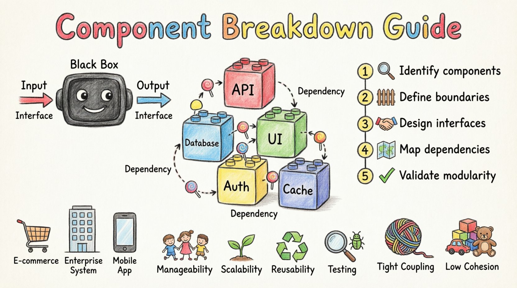
Think of a component as a black box. You know what it does (its output) and how to interact with it (its input), but the internal logic remains hidden unless necessary. This abstraction allows developers to work on different parts of a system independently.
Key Characteristics of a Component
- Modularity: It is a distinct unit of functionality.
- Encapsulation: Internal implementation details are hidden from the outside world.
- Interchangeability: It can be replaced by another component that provides the same interface without affecting the rest of the system.
- Deployment: It is a physical unit that can be distributed and installed.
📐 The Anatomy of a Component Diagram
A component diagram visualizes the organization and dependencies of these modular units. It is a structural diagram used in the Unified Modeling Language (UML). For IS students, mastering this diagram type is crucial for communicating high-level architecture to stakeholders.
A standard component diagram consists of specific elements that must be understood to create accurate models.
| Element | Description | Visual Representation |
|---|---|---|
| Component | A modular part of the system containing functionality. | Rectangle with a small tab on the top left |
| Interface | A contract defining operations provided or required. | Circle (Lollipop notation) or rectangle with text |
| Port | A designated point of interaction for a component. | Small square on the edge of a component |
| Dependency | A relationship where one component needs another. | Dashed arrow pointing to the required component |
| Association | A structural link between components. | Solid line connecting components |
🔍 Why Break Down a System?
Building a monolithic system without decomposition leads to fragility and maintenance nightmares. Component breakdown serves several strategic purposes for Information Systems.
1. Manageability
A large system is too complex for one person to understand fully. By breaking it down, teams can focus on specific modules. This reduces cognitive load and allows for parallel development.
2. Scalability
When components are independent, they can be scaled individually. If the user authentication module requires more resources, you can upgrade that specific component without rebuilding the entire payment processing system.
3. Reusability
Well-defined components can be used across different projects. A generic “Email Notification” component created for a marketing system can be integrated into a customer support system with minimal modification.
4. Testing
Testing isolated components is significantly easier than testing a whole system. Unit tests can be written for each component to ensure it functions correctly before integration.
🛠️ The Component Breakdown Process
Decomposing a system is a logical exercise that requires a top-down approach. It begins with the high-level requirements and drills down into specific functionalities. Follow these steps to perform a systematic breakdown.
Step 1: Identify Core Business Functions
Start by listing the primary goals of the system. What problems does it solve? For example, an online store system must handle orders, manage inventory, process payments, and ship goods. These are your initial candidate components.
Step 2: Define Boundaries
Assign each function to a specific component. Ensure that each component has a single responsibility. If a component handles both “Order Processing” and “Inventory Management,” it is likely too large and should be split.
Step 3: Determine Interfaces
Every component must communicate with others. Define the inputs and outputs for each module. What data does it need to start? What data does it produce? This defines the contract between components.
Step 4: Map Dependencies
Draw the relationships. Which component relies on another? For instance, the “Order Processing” component depends on the “Inventory” component to check stock. These dependencies dictate the flow of the architecture.
Step 5: Refine and Validate
Review the diagram. Are there circular dependencies? Is any component too large? Does every requirement have a corresponding component? Iteration is key to a clean design.
🔌 Understanding Interfaces and Ports
Interfaces are the glue that holds components together. They define the rules of engagement. Without clear interfaces, components become tightly coupled, making the system rigid.
Provided Interfaces
This is what a component offers to the rest of the system. It is a service it provides. For example, a Payment Gateway component provides a “Process Transaction” interface. Other components call this interface to pay for goods.
Required Interfaces
This is what a component needs to function. It is a service it requests. For example, the Shopping Cart component requires a “Calculate Tax” interface from a Tax Service component.
| Interface Type | Direction | Example |
|---|---|---|
| Provided (Lollipop) | Component -> System | Authentication Component provides “Login” |
| Required (Socket) | System -> Component | Order Component requires “Validate User” |
Ports act as the physical connection points on the component where these interfaces are exposed. A component can have multiple ports, each exposing a different interface. This allows for flexible integration.
📊 Component vs. Class Diagram
Students often confuse component diagrams with class diagrams. While both model structure, they operate at different levels of abstraction.
- Granularity: Class diagrams focus on the code level (methods, attributes). Component diagrams focus on the architectural level (modules, libraries).
- Deployment: Components are deployable units (e.g., .jar files, .dll libraries). Classes are code units within a deployment.
- Abstraction: Components hide implementation. Class diagrams reveal internal logic.
Use a class diagram when designing the internal logic of a specific component. Use a component diagram when designing the overall system structure.
⚠️ Common Mistakes in Component Modeling
Even experienced designers make errors. Being aware of these pitfalls will help you create cleaner models.
1. Tight Coupling
This occurs when components rely heavily on each other’s internal details. If you change one component, the other breaks. Aim for loose coupling where components interact only through defined interfaces.
2. High Cohesion Issues
Cohesion refers to how related the responsibilities of a single component are. If a component handles “User Login” AND “Email Marketing,” it lacks cohesion. It should be split. High cohesion means a component does one thing well.
3. Over-Engineering
Do not create a component for every single function. A small system might only need five components. Creating twenty components adds unnecessary complexity and overhead.
4. Ignoring Dependencies
Failure to map dependencies leads to runtime errors. Ensure that if Component A needs data from Component B, the link is explicitly drawn in your diagram.
✅ Checklist for IS Students
Before finalizing your component breakdown, run through this checklist to ensure quality.
- Single Responsibility: Does each component have one clear purpose?
- Clear Interfaces: Are the provided and required interfaces documented?
- No Circular Dependencies: Does Component A depend on B, and B depend on A? If so, refactor.
- Scalability: Can this component be scaled independently if needed?
- Completeness: Do all system requirements map to at least one component?
- Clarity: Can another student understand this diagram without verbal explanation?
🌐 Real-World Application Scenarios
Understanding the theory is one thing; applying it is another. Here are scenarios where component breakdown is critical.
Scenario 1: E-Commerce Platform
In a large retail system, the “Checkout” process is complex. It involves inventory checks, payment processing, tax calculation, and order confirmation. Breaking this into separate components allows the team to update the payment processor without affecting the inventory system.
Scenario 2: Enterprise Resource Planning
ERP systems integrate finance, HR, and logistics. Each area is a distinct component. The Finance component might require data from the HR component (for payroll). Clear interfaces ensure data flows correctly without the Finance team needing to know HR database schemas.
Scenario 3: Mobile Application Backend
A mobile app might connect to multiple backend services. One service handles user profiles, another handles notifications, and a third handles analytics. Component diagrams help define how the mobile client interacts with these microservices.
🔗 Relationships and Dependencies
Understanding how components relate is vital for system stability. There are two primary types of relationships to model.
Dependency
A dependency implies that a change in one component may affect the other. It is a “uses” relationship. In a diagram, this is shown as a dashed line with an open arrow. This is the most common relationship in component diagrams.
Association
An association represents a structural link. It implies that components are connected and may hold references to each other. This is shown as a solid line. Use this sparingly to avoid implying tight coupling.
🛡️ Security Considerations in Component Design
Security is often an afterthought, but it should be integrated into the component breakdown. Each component should define its security requirements.
- Authentication: Which components require user verification?
- Authorization: Which components restrict access based on user roles?
- Data Encryption: Which components handle sensitive data that must be encrypted in transit?
By marking components with security attributes, you ensure that the architecture supports a secure system from the start.
📈 Maintenance and Evolution
Systems evolve. Requirements change. A good component breakdown anticipates change. When designing components, consider how they might be replaced or updated in the future.
If a component is designed with a stable interface, you can swap its implementation without touching the rest of the system. This is the power of component-based development. It ensures that your Information System remains relevant and maintainable over years of operation.
🎓 Final Thoughts for Aspiring Architects
Creating a component breakdown is a skill that improves with practice. Start with simple systems and gradually increase complexity. Always prioritize clarity over cleverness. A diagram that is easy to understand is better than one that is technically impressive but confusing.
Remember that the goal is not just to draw a picture. The goal is to create a blueprint that guides the construction of reliable, scalable, and secure software. Use the principles of modularity and abstraction to your advantage. By mastering the art of component breakdown, you equip yourself with the foundational knowledge needed to design robust Information Systems.
Focus on the logic, respect the interfaces, and keep the dependencies minimal. These are the pillars of effective system architecture.

