


In the landscape of software architecture, clarity is paramount. A component diagram serves as a foundational artifact for visualizing the organization of software systems. It breaks down complex logic into manageable blocks, allowing teams to communicate structural relationships without getting lost in implementation details. This guide addresses the most critical inquiries regarding these diagrams, providing authoritative insights for architects, developers, and stakeholders.
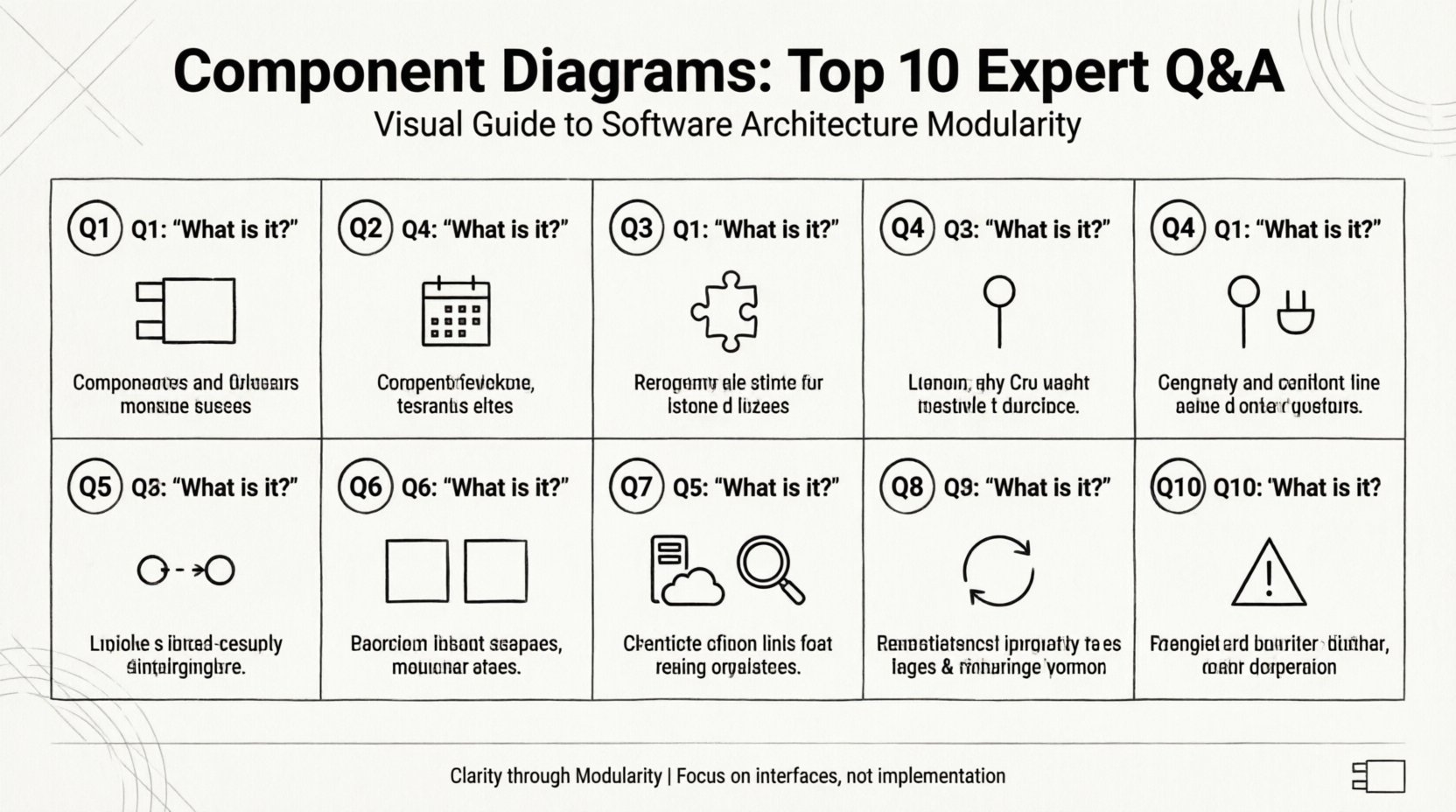
1. What Exactly Is a Component Diagram? 🤔
A component diagram represents the physical or logical components of a system. Unlike class diagrams, which focus on code structure, this model emphasizes modularity and reuse. It depicts components as rectangular boxes with a specific icon (two small rectangles on the left side) and labels them with their names.
- Visual Representation: It shows how components are wired together.
- Abstraction Level: It operates at a higher level than class diagrams.
- Focus: It highlights interfaces and dependencies rather than internal logic.
This modeling technique is essential for understanding system boundaries. It answers the question: “What makes up this system?” rather than “How does this specific function work?”.
2. When Should You Use a Component Diagram? 📅
Timing is crucial in system design. You should deploy this diagram during the early design phases or when refactoring legacy systems. Specific scenarios include:
- Architectural Reviews: When presenting the high-level structure to stakeholders.
- Integration Planning: When defining how third-party modules interact with internal logic.
- Team Handoffs: When transferring responsibility between frontend and backend teams.
- Documentation: Creating a reference guide for maintenance and onboarding.
Using this diagram during the coding phase is often too late, as the structure is already fixed. It is most effective when the architecture is still malleable.
3. What Are the Key Elements of a Component Diagram? 🔑
Understanding the notation is the first step to accurate modeling. The core elements include:
- Components: The modular units of the system, often represented by a rectangle with a stereotype label.
- Interfaces: Defined sets of operations provided or required by a component.
- Connections: Lines linking components to interfaces or other components.
- Ports: Specific points where a component connects to its environment.
Each element serves a distinct purpose. Interfaces define the contract, while components define the implementation. Connections define the flow of control or data.
4. How Do Provided and Required Interfaces Differ? ⚡
Interfaces are the glue that holds components together. Distinguishing between what a component offers and what it needs is vital.
| Interface Type | Symbol | Function |
|---|---|---|
| Provided Interface | Lollipop (Circle) | |
| Required Interface | Socket (Half-Circle) |
Visualizing these symbols allows you to see dependencies at a glance. A component cannot function if its required interfaces are not connected to a provider. This relationship ensures loose coupling, allowing components to swap implementations as long as the interface remains consistent.
5. What Types of Relationships Exist Between Components? 🔗
Relationships define the nature of interaction. The primary types include:
- Dependency: A usage relationship. If one component changes, it may affect the other. Represented by a dashed arrow.
- Association: A structural link indicating a stronger relationship. Represented by a solid line.
- Realization: One component implements the interface of another. Represented by a dashed line with a hollow triangle.
- Generalization: Inheritance relationships between components. Represented by a solid line with a hollow triangle.
Understanding these distinctions prevents architectural ambiguity. For instance, confusing a dependency with an association can lead to tight coupling, making the system difficult to maintain.
6. How Does a Component Diagram Differ from a Class Diagram? 🆚
While both describe structure, their scope varies significantly.
- Granularity: Class diagrams focus on individual classes and methods. Component diagrams focus on subsystems and modules.
- Implementation: Class diagrams often expose internal logic. Component diagrams hide internal logic behind interfaces.
- Stability: Components are more stable than classes. Classes change frequently; components change rarely.
Use a class diagram when designing specific algorithms. Use a component diagram when designing the system topology. They are complementary, not interchangeable.
7. How Do Component Diagrams Support Deployment? 🖥️
Deployment diagrams show the hardware and software infrastructure. Component diagrams bridge the gap between logical design and physical deployment.
When mapping components to nodes:
- Scalability: Identify which components need replication.
- Load Balancing: Determine where traffic should be routed.
- Security Zones: Define which components reside in protected environments.
This alignment ensures that the logical model reflects the physical reality. It helps in planning resource allocation and network topology before any code is written.
8. What Is the Ideal Level of Granularity? 🔍
Granularity refers to the size of the components depicted. Too large, and the diagram is useless; too small, and it becomes a class diagram in disguise.
Best practices for sizing include:
- Functional Cohesion: Each component should perform a single, well-defined function.
- Team Boundaries: Components should align with development teams.
- Deployment Units: Components should often map to deployable artifacts (e.g., libraries, services).
Aim for components that can be developed and tested independently. If a component requires too much coordination to modify, it is likely too complex.
9. How Do You Maintain Component Diagrams Over Time? 🔄
Diagrams become obsolete quickly if not maintained. Keeping them relevant requires a disciplined approach.
- Version Control: Store diagrams alongside code repositories.
- Change Management: Update the diagram whenever a major architectural change occurs.
- Automation: Use tools that generate diagrams from code to reduce manual effort.
- Regular Reviews: Schedule periodic audits to ensure accuracy.
Ignoring updates leads to documentation debt. Developers will stop trusting the diagrams, rendering them useless for future reference.
10. What Are the Common Pitfalls to Avoid? ⚠️
Even experienced architects make mistakes. Avoiding these common errors ensures clarity.
- Over-Modeling: Creating diagrams with too many components obscures the main architecture.
- Ignoring Interfaces: Focusing only on components without defining interfaces leads to coupling.
- Inconsistent Naming: Using different terms for the same concept confuses readers.
- Lack of Context: Not showing the external environment makes the system look isolated.
By steering clear of these traps, you ensure the diagram remains a valuable asset rather than a burden.
Summary of Key Takeaways 📝
Component diagrams are indispensable for managing complexity in software systems. They provide a clear view of modularity, interfaces, and dependencies. By adhering to best practices regarding granularity, maintenance, and notation, teams can leverage these diagrams to build robust, scalable architectures.
Remember that a diagram is a tool for communication. Its value lies in the clarity it brings to the team, not in the aesthetic perfection of the drawing. Focus on accuracy and readability to maximize the return on investment for your documentation efforts.

