


In the complex landscape of software architecture, clarity is paramount. A component diagram serves as a critical blueprint, illustrating the physical and logical structure of a system without getting bogged down in implementation details. This guide explores the lifecycle of a component, moving from high-level interfaces down to physical deployments. We examine how systems are structured, how they interact, and how they are delivered to end users.
Understanding the Component Unit 🏗️
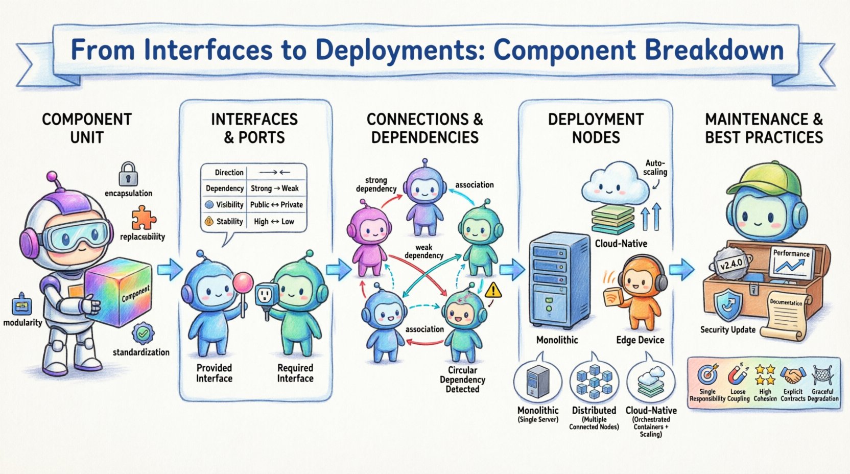
A component is a modular, replaceable part of a system that encapsulates functionality and data. It represents a significant unit of implementation. Unlike a class, which is a code-level concept, a component is often a physical unit, such as a library, a service, or a module. It exposes its functionality through interfaces while hiding internal complexity.
Key characteristics of a robust component include:
- Encapsulation: Internal state and logic are hidden from external observers.
- Modularity: The component can be developed, tested, and deployed independently.
- Replaceability: It can be swapped with another component that implements the same interface.
- Standardization: It adheres to defined protocols for interaction.
When designing a system, breaking it down into components allows teams to manage complexity. Instead of viewing the application as a monolith, architects identify distinct responsibilities. Each component should have a single, well-defined purpose. This separation of concerns reduces coupling and enhances maintainability.
Interfaces and Ports: The Communication Layer 🔗
Interfaces define the contract between a component and its environment. They specify what a component can do without revealing how it does it. In modeling, interfaces are often represented as ports. Ports act as the points of contact where interactions occur.
There are two primary types of interfaces to consider:
- Provided Interface: This is the service a component offers to others. It is often depicted as a lollipop shape in diagrams. Other components connect to this interface to utilize functionality.
- Required Interface: This is the service a component needs from others to function. It is often depicted as a socket shape. The component must find a provider to fulfill this requirement.
Understanding the distinction between these two is vital for system integration. A mismatch between a required interface and a provided interface leads to runtime failures. The following table outlines the differences:
| Feature | Provided Interface | Required Interface |
|---|---|---|
| Direction | Outbound (Offers service) | Inbound (Needs service) |
| Dependency | Others depend on this | This depends on others |
| Visibility | Publicly accessible | Internal or external consumer |
| Stability | Changes break consumers | Changes break the component |
When defining these interfaces, precision is key. Ambiguity in method signatures or data formats creates friction during integration. Contracts should be versioned to manage evolution. This ensures that updates to a component do not break dependent systems unexpectedly.
Connections and Dependencies 🛠️
Connections link components together, enabling data flow and control flow. A connection represents a relationship where one component uses another. It is crucial to manage the nature of these dependencies to prevent tight coupling.
Dependencies can be categorized as:
- Strong Dependencies: The component cannot function without the other. This usually implies a direct class or library link.
- Weak Dependencies: The component can function with a fallback or alternative implementation.
- Association: A general relationship indicating that objects of one component know about objects of another.
- Aggregation: A whole-part relationship where the part can exist independently of the whole.
Minimizing strong dependencies improves system resilience. If one component fails, the impact should be contained. Using interfaces to mediate connections helps achieve this. Instead of connecting Component A directly to Component B’s implementation, they connect via an interface. This allows Component B to be replaced without affecting Component A.
Architects often use dependency graphs to visualize these relationships. These graphs highlight cycles, which are often indicative of design flaws. A cycle occurs when Component A depends on B, and B depends on A. This creates a circular reference that can lead to initialization errors and tight coupling.
Deployment Nodes and Artifacts 🚀
Once a component is designed, it must be deployed. Deployment diagrams extend the component model to the physical infrastructure. They show how software is distributed across hardware nodes.
A deployment node represents a physical or virtual computing resource. Examples include servers, containers, or edge devices. Each node has specific characteristics, such as processing power, memory, and operating system constraints.
Artifacts are the physical representations of components. They include files, executables, scripts, or binaries. An artifact is deployed to a node to become a running instance. The mapping between artifacts and nodes is critical for understanding the runtime environment.
Consider the following deployment scenarios:
- Monolithic: All artifacts are deployed to a single node. This simplifies networking but creates a single point of failure.
- Distributed: Artifacts are spread across multiple nodes. This improves scalability and fault tolerance but increases complexity in configuration.
- Cloud-Native: Artifacts are containerized and orchestrated. This allows for dynamic scaling and resource optimization.
When planning deployment, consider the environment. Development, testing, and production environments often require different configurations. Artifacts must be packaged in a way that supports these variations. Configuration management tools help standardize this process without hardcoding environment-specific details.
Maintaining Component Integrity 📝
Once a system is live, components require maintenance. This involves monitoring, updating, and refactoring. A component that cannot be maintained becomes technical debt. Regular reviews ensure that the component still meets its original requirements.
Key maintenance activities include:
- Version Control: Tracking changes to interfaces and artifacts. This ensures backward compatibility where possible.
- Performance Monitoring: Observing resource usage. High latency or memory leaks indicate a need for optimization.
- Dependency Updates: Keeping underlying libraries secure and up to date. This reduces vulnerability risks.
- Documentation: Updating diagrams and specs as the system evolves. Outdated diagrams lead to confusion.
Refactoring is often necessary when requirements change. If a component grows too large, it may need to be split. This is known as decomposition. Conversely, if components are too small and fragmented, they may need to be merged. The goal is to maintain a balance between granularity and cohesion.
Common Pitfalls in Modeling ⚠️
Even experienced architects encounter challenges when modeling systems. Recognizing these pitfalls early saves time and resources. Below are common issues to avoid.
1. Over-Abstraction: Creating interfaces that are too generic. If an interface does not reflect actual usage, it becomes a burden. Keep interfaces specific to the needs of the consumer.
2. Hidden Dependencies: Relying on services that are not explicitly modeled. If a component calls a service not shown in the diagram, the diagram is incomplete. All external dependencies should be visible.
3. Ignoring Non-Functional Requirements: Focusing only on functionality while neglecting performance, security, or availability. A component might work logically but fail under load. Model constraints explicitly.
4. Inconsistent Notation: Using different symbols for similar concepts across diagrams. Consistency helps readers understand the system quickly. Stick to a standard notation.
5. Static Snapshots: Treating the diagram as a one-time deliverable. Systems evolve, and diagrams should too. Treat them as living documents.
Best Practices for Component Design 📊
To ensure a system is robust and scalable, adhere to established design principles. These practices guide the creation of components that are easy to understand and modify.
- Single Responsibility: Each component should handle one distinct business capability. This makes testing and debugging easier.
- Loose Coupling: Minimize dependencies between components. Use interfaces to decouple implementation details.
- High Cohesion: Keep related functionality together within a component. This reduces the surface area for changes.
- Explicit Contracts: Define clear input and output specifications. Avoid implicit assumptions about data formats.
- Graceful Degradation: Design components to fail safely. If a dependency is unavailable, the system should remain functional.
Final Considerations 🔍
Building a system is an iterative process. The component breakdown is not a static artifact but a tool for communication and planning. It helps stakeholders visualize the architecture and identify risks before they become problems.
Focus on clarity. A diagram should be understandable by both developers and non-technical stakeholders. Use consistent naming conventions. Avoid jargon where simple terms suffice. Ensure that the deployment strategy aligns with the component design.
As technology evolves, so do the patterns of interaction. Cloud services, microservices, and serverless architectures introduce new considerations. However, the fundamental principles of interfaces, components, and deployment remain relevant. By grounding your design in these core concepts, you create systems that are adaptable and resilient.
Remember that the goal is not just to build a system, but to build a system that can be sustained. Careful attention to the breakdown of components and their interactions lays the foundation for long-term success. Regularly revisit your diagrams and validate them against the actual running system. This feedback loop ensures that the model remains accurate and useful.
By following these guidelines, teams can navigate the complexity of modern software architecture with confidence. The path from interface to deployment is well-trodden, but it requires diligence and precision at every step.

