


Systems Modeling Language (SysML) provides a robust framework for describing complex systems, yet the complexity of the language itself often introduces specific challenges. When building models, inconsistencies can creep in, leading to validation failures or incorrect system behavior predictions. This guide focuses on identifying common pitfalls and applying systematic methods to resolve them efficiently. By understanding the root causes of modeling errors, engineers can maintain high-quality models without relying on external tools to fix underlying logic issues.
📊 Understanding the Scope of Modeling Errors
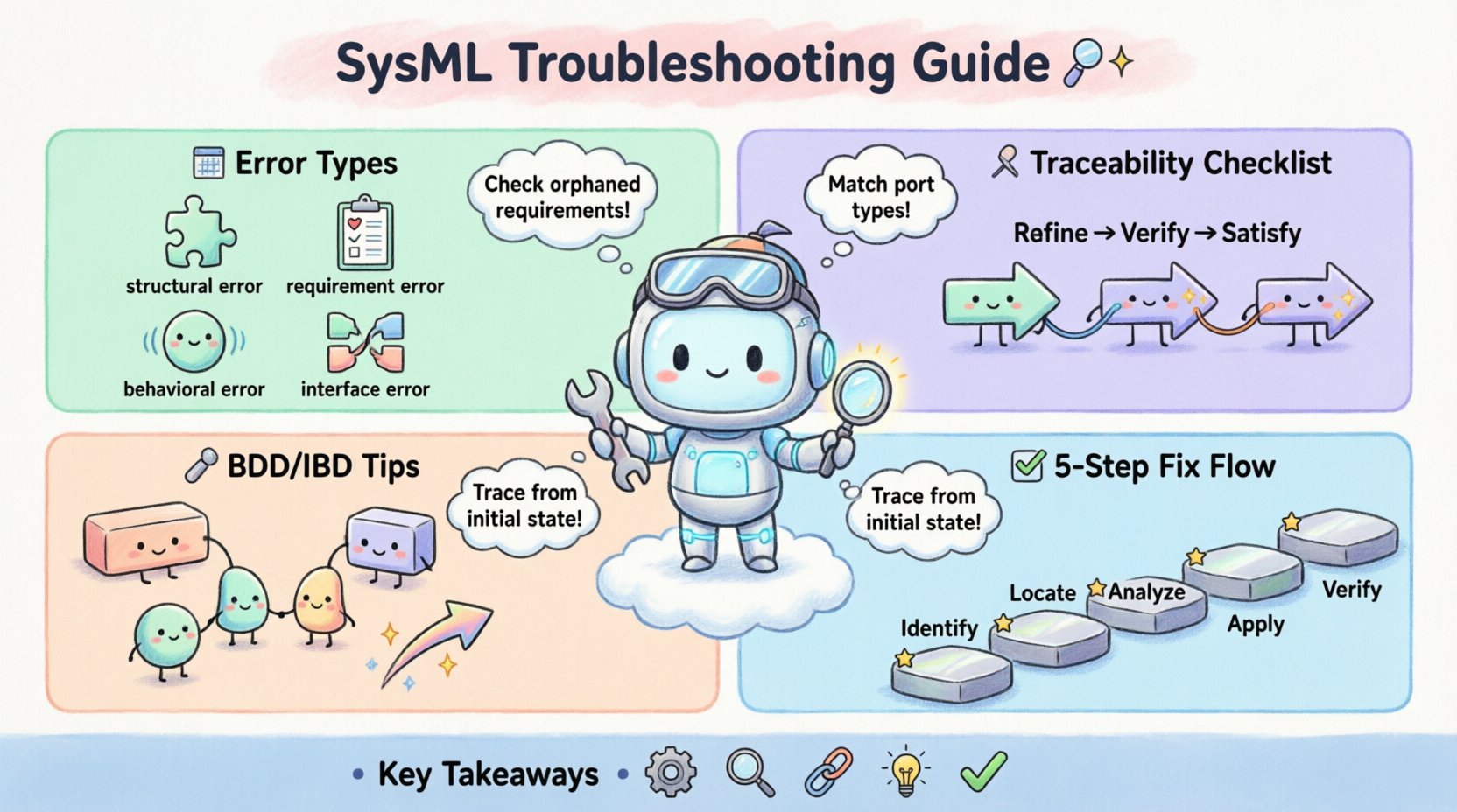
Modeling errors in SysML typically fall into several categories: structural inconsistencies, requirement mismatches, behavioral logic flaws, and interface definition errors. Each category requires a distinct approach to diagnosis. Recognizing the symptoms early prevents compounding issues later in the engineering lifecycle. A model that compiles successfully but contains logical gaps is often harder to debug than one that fails validation immediately.
- Structural Errors: These involve incorrect relationships between blocks, properties, and connectors.
- Requirement Errors: Issues where requirements are not linked correctly to design elements.
- Behavioral Errors: Flaws in state machines, activity diagrams, or sequence interactions.
- Interface Errors: Mismatches in ports, flows, and value types.
🧩 Requirement Traceability and Linkage
One of the most frequent sources of trouble arises from broken traceability links. In SysML, requirements must be explicitly linked to design elements to verify coverage. When these links are missing or incorrect, the model cannot demonstrate that the system meets its intended goals.
Common Requirement Issues
- Orphaned Requirements: Requirements that exist in the diagram but have no downstream traceability.
- Circular Dependencies: A requirement that references another requirement in a loop, creating confusion in validation.
- Missing Verifications: Requirements that lack associated verification criteria or test cases.
To diagnose requirement issues, review the Requirement Diagram. Ensure every requirement has a clear relationship to a Block or Parameter. Use the following checklist during your review:
- Verify that all
Refinerelationships point to the correct parent requirement. - Check that
Verifyrelationships link requirements to test cases or behaviors. - Ensure
Satisfyrelationships connect requirements to design blocks.
When a link is broken, the model environment often flags it as a warning. Do not ignore these warnings. Trace the path from the top-level requirement down to the implementation details. If a requirement cannot be satisfied by the current design, it may need to be revised or decomposed.
📐 Structural Diagram Integrity (BDD & IBD)
The Block Definition Diagram (BDD) and Internal Block Diagram (IBD) form the backbone of the system architecture. Errors here propagate throughout the entire model, causing downstream failures in behavioral diagrams.
Block Definition Diagram (BDD) Errors
- Incorrect Generalization: A block inheriting from another that it should not. This creates logical contradictions in the type hierarchy.
- Misconfigured Aggregation: Using composition instead of aggregation, or vice versa, which affects lifecycle management.
- Redundant Properties: Defining properties that already exist in a parent block without overriding them correctly.
Internal Block Diagram (IBD) Errors
The IBD describes how blocks interact internally. A common mistake is connecting parts that do not have compatible interfaces.
| Error Type | Symptom | Impact |
|---|---|---|
| Port Mismatch | Flow cannot be established | Signal or data loss in simulation |
| Missing Part | Reference to undefined block | Compilation failure |
| Type Incompatibility | Value types do not align | Invalid parameter values |
| Unconnected Flow | Flow starts but ends nowhere | Incomplete data path |
When troubleshooting IBD errors, focus on the connectors. Ensure that the flow direction matches the data or signal direction. If a flow is bidirectional, confirm that both ports support this capability. Use the type system to validate that the data types match exactly.
⚡ Behavioral Consistency and Flow
Behavioral diagrams, such as State Machines, Activity Diagrams, and Sequence Diagrams, define how the system acts over time. Errors here often manifest as logic loops or deadlocks.
State Machine Troubleshooting
- Unreachable States: States that cannot be entered from the initial state.
- Missing Transitions: States without defined exit paths, leading to potential hangs.
- Guard Condition Errors: Boolean expressions that are always false or undefined.
To resolve state machine issues, trace the execution path from the initial state. If a state cannot be reached, add the necessary transition. Verify that guard conditions are syntactically correct and logically sound. If a guard relies on a parameter, ensure that parameter is available at the time of transition.
Activity Diagram Troubleshooting
- Object Flow Conflicts: Multiple inputs to a single action without a clear order.
- Token Accumulation: Actions that accumulate tokens without consuming them.
- Control Flow Loops: Infinite loops that prevent model completion.
When debugging activity diagrams, check the object flows. Ensure that inputs are produced before they are consumed. If an action requires multiple inputs, verify that the preceding actions provide them. Use the execution simulation feature to observe token movement.
🔗 Interface and Port Connections
Interfaces define the contract between system components. Port connections are the physical realization of these contracts. Mismatches here are common and can be difficult to spot visually.
Interface Mismatch Diagnosis
- Operation Name Errors: The port expects an operation named
Start, but the block providesInit. - Parameter Type Errors: The port expects a
Realvalue, but the block provides anInteger. - Direction Errors: The port is defined as
in, but the connection tries to pushout.
To fix interface errors, compare the interface definition against the port usage. Ensure that the interface is correctly typed. If the interface is generic, check the specific implementation. Use the type inspector to view the exact signature of the operations.
🧪 Validation and Verification Processes
Once structural and behavioral issues are resolved, validation ensures the model meets its goals. Verification confirms that the model is built correctly.
Validation Steps
- Requirement Coverage: Check if all requirements are satisfied.
- Constraint Satisfaction: Verify that constraints are met.
- Performance Analysis: Run simulations to check performance metrics.
Verification Steps
- Syntax Check: Ensure the model compiles without errors.
- Consistency Check: Verify that diagrams are consistent with each other.
- Traceability Check: Ensure all links are intact.
Do not skip these steps. A model that looks correct visually may fail validation when analyzed by the system. Use automated validation scripts where possible to reduce manual effort.
🔄 Continuous Model Maintenance
Maintaining a SysML model is an ongoing process. As requirements change, the model must evolve. Regular reviews help identify drift and inconsistencies.
Best Practices for Maintenance
- Version Control: Track changes to the model over time.
- Documentation: Add comments to explain complex logic.
- Regular Audits: Schedule periodic reviews of the model structure.
When updating the model, check for broken links. Update requirements and propagate changes to downstream elements. If a block is renamed, ensure all references are updated. This prevents orphaned elements from cluttering the model.
🛡️ Advanced Troubleshooting Techniques
For complex models, standard troubleshooting may not be enough. Advanced techniques involve deep inspection of the model metadata.
- Metadata Inspection: Review the underlying data structure of blocks and properties.
- Dependency Analysis: Map out dependencies between elements to find hidden issues.
- Simulation Debugging: Use simulation logs to trace execution failures.
These techniques require a deep understanding of the modeling language. They are best applied when standard fixes fail. Use them sparingly to avoid unnecessary complexity.
📝 Summary of Diagnostic Steps
When facing a modeling error, follow this systematic approach:
- Identify the Error: Read the error message carefully.
- Locate the Source: Navigate to the element causing the error.
- Analyze the Context: Check surrounding elements and relationships.
- Apply the Fix: Correct the relationship or definition.
- Verify the Solution: Run validation to ensure the error is resolved.
This method reduces guesswork and increases efficiency. It ensures that fixes are targeted and effective.
🚀 Moving Forward
Effective SysML troubleshooting requires patience and attention to detail. By focusing on the structural and logical integrity of the model, engineers can build reliable systems. Regular practice with these techniques will improve speed and accuracy. Keep the model clean and consistent to avoid future headaches.
Remember that a model is a living document. It evolves with the system. Stay vigilant and keep the lines of communication open between the model and the requirements. This ensures that the final system meets all necessary criteria.
🔑 Key Takeaways
- Traceability links are critical for requirement satisfaction.
- Structural errors in BDD and IBD propagate to behavioral diagrams.
- Interface mismatches are a common source of connection failures.
- Validation and verification must be performed regularly.
- Maintaining the model is as important as building it.
Apply these principles to your next project. A well-maintained model saves time and resources in the long run.

