


Systems engineering often feels like navigating a foggy landscape without a map. When you are tasked with designing a critical infrastructure component like a multi-story elevator system, the stakes are incredibly high. A single oversight in logic or interface definition can lead to costly delays or, worse, safety hazards. This article details a practical journey where a junior engineer utilized Systems Modeling Language (SysML) to structure a complex elevator project. The goal was not just to draw diagrams, but to create a living document that connects requirements, structure, and behavior into a cohesive whole.
By avoiding proprietary software limitations and focusing on the core language capabilities, this case study demonstrates how standard SysML constructs solve real-world engineering problems. We will walk through the modeling process step-by-step, examining the specific diagram types used, the data flow established, and the challenges overcome during the development phase.
📋 Project Context and Scope
The project involved the design of a hydraulic elevator system for a mid-rise commercial building. The system needed to handle specific passenger loads, operate within strict time limits for door closure, and integrate with a building management system. The scope was broad, requiring coordination between mechanical components, electrical controls, and software logic.
Without a structured modeling approach, requirements often become siloed. Engineers working on the motor might miss a constraint defined by the door sensor team. SysML provides a unified framework to bridge these gaps. The junior engineer started by defining the system boundary and identifying the key stakeholders.
🎯 Key System Objectives
- Ensure passenger safety during all operational states.
- Optimize energy consumption during peak traffic hours.
- Maintain a response time of under 2 seconds from button press to door opening.
- Provide clear traceability from high-level needs to physical components.
These objectives formed the foundation for the requirements model. Each objective was broken down into actionable statements that could be verified later in the design process.
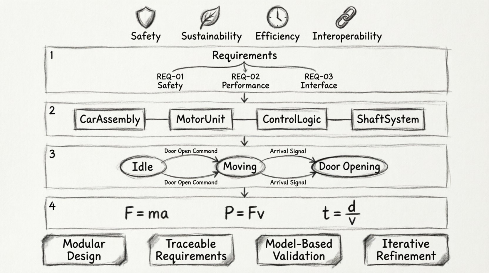
🔗 Phase 1: Requirements Engineering
The first step in any systems engineering effort is capturing what the system must do. In SysML, this is handled primarily through the Requirements Diagram and the Requirement element. This phase is crucial because it sets the rules for the rest of the model. If the requirements are vague, the structural and behavioral models will lack direction.
The engineer created a hierarchical structure for the requirements. Top-level requirements were decomposed into sub-requirements. This decomposition allowed for a granular view of the system’s obligations.
📝 Requirement Breakdown
- REQ-01: Safety
- REQ-01.1: The system must stop if the door is obstructed.
- REQ-01.2: The system must alarm if the motor overheats.
- REQ-02: Performance
- REQ-02.1: Maximum speed must not exceed 2 meters per second.
- REQ-02.2: Door closing time must be between 3 and 5 seconds.
- REQ-03: Interface
- REQ-03.1: The controller must send status updates every 500 milliseconds.
Each requirement was tagged with a unique identifier. This identifier was later linked to verification activities. The engineer used the “Refine” relationship to connect high-level needs to specific design elements. This created a traceability matrix that could be audited by safety inspectors.
🧱 Phase 2: Structural Modeling
Once the requirements were established, the focus shifted to structure. The Internal Block Diagram (IBD) was the primary tool used to visualize the physical composition of the elevator system. Unlike traditional flowcharts, IBDs show how parts interact through connectors and ports.
The model was divided into major subsystems. This modularity allowed the engineer to work on the door mechanism without needing to load the entire motor controller logic into memory.
🏗️ System Composition
| Block Name | Description | Key Interfaces |
|---|---|---|
| CarAssembly | The cabin structure and internal controls | DoorInterface, WeightSensor |
| MotorUnit | Hydraulic pump and piston assembly | PressureControl, PowerSupply |
| ControlLogic | Software and hardware controller | ButtonInput, SafetySensor |
| ShaftSystem | Physical guide rails and housing | MechanicalMount, Ventilation |
Each block was assigned properties that defined its data. For example, the MotorUnit block included a property for pressure and a property for temperature. These properties were typed to ensure consistency across the model. A property typed as Pressure would always carry units of PSI or Bar, preventing unit conversion errors later.
Connectors were used to define the flow of information and power between these blocks. The engineer identified two types of connectors:
- Flow Connectors: Used for physical energy, such as hydraulic fluid or electricity.
- Reference Connectors: Used for logical links, such as a signal indicating that a button has been pressed.
This distinction was vital for simulation. The simulation engine needed to know which connections required physical modeling and which required logical evaluation. By separating these flows in the IBD, the engineer ensured that the model remained performant.
⚙️ Phase 3: Behavioral Modeling
Structure tells us what the system is made of, but behavior tells us what it does. The elevator system has complex states that change based on external inputs. A State Machine Diagram was selected to represent the lifecycle of the car.
🔄 State Machine Logic
The state machine defined distinct states such as Idle, Moving, Door Opening, and Door Closed. Transitions between these states were triggered by events. For instance, the transition from Idle to Moving required the event ButtonPressed and the condition DoorClosed.
Inside the Door Opening state, an activity occurred. The engineer used an Activity Diagram to detail the steps within this state. This allowed for a clear view of the sequence:
- Receive signal to open.
- Check for obstruction.
- Activate motor.
- Wait for limit switch.
- Stop motor.
Sequence diagrams were also employed to validate the interaction between the ControlLogic and the SafetySensor. This visualized the timing of messages. It revealed a potential race condition where the door might close before the safety beam was fully activated.
📉 Sequence Interaction
- User presses floor button.
- Controller activates motor.
- Car reaches floor.
- Car stops.
- Controller checks safety beam.
- If clear, signal door to open.
- If blocked, signal door to stay closed.
This level of detail helped the engineer identify edge cases early. Without the sequence diagram, the interaction between the sensor and the controller might have been assumed to be instantaneous, which is rarely the case in physical hardware.
📐 Phase 4: Parametric Modeling
One of the most powerful features of SysML is the ability to model constraints and calculations using Parametric Diagrams. This was essential for verifying the physical limits of the elevator system. The engineer needed to ensure that the motor could lift the maximum load within the required time frame.
Constraint blocks were defined for physical laws. A constraint block for NewtonianMotion was created, containing equations for force, mass, and acceleration. These equations were then linked to the properties in the Structural Model.
🧮 Constraint Relationships
- Force = Mass × Acceleration
- Power = Force × Velocity
- Time = Distance / Velocity
By linking these equations to the model properties, the engineer could run simulations to verify if the system met the performance requirements. If the calculated force exceeded the motor capacity, the model would flag a violation. This is a form of Model-Based Verification.
This approach reduced the need for physical prototypes in the early stages. The engineer could adjust the mass of the car or the power of the motor in the model and instantly see the impact on the required time. This iterative process saved significant time and resources.
🚧 Challenges Encountered
Modeling a complex system is not without its difficulties. The junior engineer faced several hurdles during this project. Addressing these challenges is just as important as the success of the final model.
🔍 Traceability Management
Maintaining links between requirements and model elements proved difficult as the model grew. A requirement might change, requiring updates to the structure, behavior, and parametrics. If these links were not managed carefully, the model became inconsistent.
To solve this, the engineer adopted a strict naming convention. All model elements were named to reflect their parent requirement. When a requirement was updated, the name change triggered a review of all linked elements. This discipline prevented orphaned requirements.
🧩 Model Complexity
As more subsystems were added, the diagrams became cluttered. It was hard to read an Internal Block Diagram with fifty connections. The engineer addressed this by using views. A view is a subset of the model shown in a specific diagram.
- Mechanical View: Shows only physical connections.
- Electrical View: Shows only signal flows.
- Logic View: Shows only control logic.
This separation made the documentation readable for different stakeholders. The mechanical team could focus on the Mechanical View without being distracted by electrical signals.
🔄 Version Control
Managing changes to the model was a significant challenge. Traditional version control systems work well for text, but modeling tools often store data in binary formats. This made it hard to see exactly what changed between versions.
The engineer implemented a manual review process for every model change. A change log was maintained alongside the model. Every modification was documented with the reason for the change and the person responsible. This audit trail was essential for safety certification.
💡 Lessons Learned and Best Practices
After completing the elevator system model, several insights emerged that could benefit other systems engineers.
🌟 Start Small
Do not attempt to model the entire system at once. Start with the core requirements and a simple structure. Expand the model incrementally. This approach prevents the model from becoming unmanageable early in the process.
🌟 Define Standards Early
Establish naming conventions and modeling standards before beginning. Decide on how to name ports, how to structure packages, and how to link requirements. Consistency is the key to maintaining a large model over time.
🌟 Verify Often
Do not wait until the end of the project to verify the design. Run simulations and checks at every phase. If the parametric model shows a violation, fix the design immediately. Catching errors early reduces rework costs significantly.
🌟 Focus on Semantics
Ensure that the model conveys meaning, not just shape. A diagram should explain the system, not just look complex. Use labels and descriptions to clarify the intent of every connection and block. The model is a communication tool, not just a design artifact.
📊 Summary of Modeling Elements
To recap the technical elements used in this case study, the following table summarizes the diagram types and their specific applications.
| Diagram Type | Primary Use Case | Key Benefit |
|---|---|---|
| Requirements Diagram | Linking needs to design | Ensures traceability |
| Internal Block Diagram | Physical composition | Visualizes interfaces |
| State Machine Diagram | Operational states | Clarifies lifecycle |
| Sequence Diagram | Timing and interaction | Identifies race conditions |
| Parametric Diagram | Calculations and constraints | Validates physical limits |
Each diagram type served a distinct purpose. Using them in isolation would have resulted in a fragmented understanding of the system. Combining them created a comprehensive representation of the elevator system.
🏁 Final Thoughts on Systems Modeling
This case study illustrates that SysML is a practical tool for engineering complex systems. It is not merely a theoretical exercise but a method for reducing risk and improving communication. The junior engineer successfully modeled a critical system by adhering to standard practices and focusing on the relationships between requirements, structure, and behavior.
The elevator system model is now a living artifact. As the project moves from design to implementation, the model serves as the source of truth. Changes in the physical hardware are reflected in the model, and changes in the model are validated against the requirements.
For other engineers looking to adopt similar methods, the path is clear. Start with the requirements. Build the structure. Define the behavior. Verify the constraints. Maintain the traceability. By following this disciplined approach, you can manage complexity and deliver systems that are safe, efficient, and reliable.

