


Entering the world of Systems Modeling Language (SysML) can feel like stepping into a dense forest without a map. Many engineers and architects hesitate at the threshold, fearing the complexity of notation, the rigidity of syntax, and the sheer volume of diagrams required to describe a system. However, the truth is far simpler. You do not need to become a notation expert overnight to derive value. You need a clear path. This guide provides that path. It is designed to help you construct your first system model quickly, focusing on clarity and structure rather than getting lost in technical minutiae.
Model-Based Systems Engineering (MBSE) is not about replacing documents with pictures. It is about creating a single source of truth that connects requirements, structure, behavior, and performance. When you build a model, you are building a logic framework. This framework allows you to trace a requirement from a stakeholder need all the way down to a specific component property. In this article, we will strip away the noise and focus on the essential mechanics of SysML.
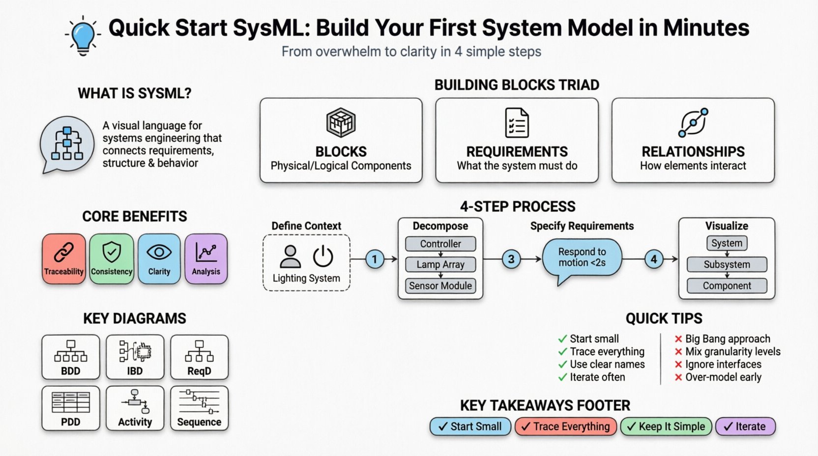
🧩 What is SysML and Why Does It Matter?
SysML is a general-purpose modeling language for systems engineering applications. It is an extension of the Unified Modeling Language (UML), tailored to handle the specific needs of systems engineering. While UML focuses heavily on software design, SysML expands the scope to include physical parts, requirements, and parametric constraints.
Why adopt this approach? Consider the traditional workflow. You have a requirements document in Word, a block diagram in Visio, and a simulation model in MATLAB. These artifacts often drift apart. A change in one does not automatically update the others. This leads to errors, rework, and misalignment. SysML integrates these views. When you model in SysML, the relationships between elements are explicit. If you change a block, the model knows which requirements depend on that block.
Here are the core benefits of starting your modeling journey:
- Traceability: Connect requirements directly to system components.
- Consistency: Ensure the design matches the intent defined in requirements.
- Clarity: Visual representations reduce ambiguity in complex system interactions.
- Analysis: Enable early validation of performance and behavior before physical prototyping.
🛠️ Core Building Blocks of a SysML Model
Before drawing diagrams, you must understand the vocabulary. SysML is built on a set of fundamental concepts. Think of these as the atoms of your system model. Every diagram you create will eventually be composed of these elements.
1. Blocks
A Block is the most fundamental element. It represents a physical or logical component of your system. It could be a physical part like a sensor, a logical entity like a user, or a subsystem like a guidance module. Blocks define the identity of your system.
- Properties: Characteristics or parts contained within a block.
- Operations: Functions or actions the block can perform.
- Attributes: Data values associated with the block.
2. Requirements
Requirements define what the system must do or what constraints it must satisfy. In a model, a requirement is a distinct element that can be traced to other elements. This is crucial for validation. A requirement is not just text; it is a node in a network of logic.
- Stakeholder Requirements: High-level needs from the client or user.
- System Requirements: Technical specifications derived from stakeholder needs.
- Internal Requirements: Constraints specific to a subsystem.
3. Relationships
Relationships define how blocks and requirements interact. Without relationships, you have a pile of disconnected elements. Relationships create the structure.
- Association: A general link between two blocks.
- Aggregation: A “whole-part” relationship where the parts can exist independently.
- Composition: A strong “whole-part” relationship where parts cannot exist without the whole.
- Refines: Links a detailed requirement to a high-level requirement.
- Allocates: Links a requirement to a block that satisfies it.
📐 Step-by-Step: Creating Your First Model
Now that the vocabulary is clear, let us walk through the process of creating a model. We will assume a scenario: designing a basic automated lighting system. This example is simple enough to grasp quickly but complex enough to demonstrate the modeling principles.
Step 1: Define the System Context
Start by defining the boundary of your system. What is inside the box, and what is outside? This is often called the “Context Diagram.”
- Create a new Block named “Automated Lighting System”.
- Identify external actors or systems. For this example, let’s define “User” and “Power Source”.
- Draw associations between the “User” and the “Lighting System”.
- Document the nature of the interaction. The user provides input; the system provides light.
Step 2: Decompose the System
A single block is often too abstract. You need to break it down into manageable subsystems. This is done using Composition.
- Right-click the “Automated Lighting System” block.
- Create a new Block property for “Controller”.
- Create a new Block property for “Lamp Array”.
- Create a new Block property for “Sensor Module”.
- Ensure the type of relationship is Composition. This indicates that if the Lighting System is destroyed, these subsystems lose their context within that system.
Step 3: Specify Requirements
Requirements drive the design. You cannot design effectively without constraints. Create a Requirement element for the system.
- Name: “Lighting shall respond to motion within 2 seconds”.
- Type: Functional Requirement.
- Trace: Link this requirement to the “Controller” block using an Allocation relationship.
- Reason: This ensures that the design of the controller is validated against the performance constraint.
Step 4: Visualize the Structure
Now that you have blocks and requirements, you need to visualize them. The primary diagram for structure is the Block Definition Diagram (BDD).
- Open a new BDD view.
- Drag the “Automated Lighting System” block onto the canvas.
- Drag the “Controller”, “Lamp Array”, and “Sensor Module” inside it.
- Draw lines to represent the associations you defined in Step 1.
- Save and review. Does the visual structure match your mental model of the system?
📊 Understanding Key SysML Diagrams
SysML provides a variety of diagram types to capture different aspects of a system. Using the right diagram at the right time is key to avoiding clutter. Below is a breakdown of the most critical diagrams for a beginner.
| Diagram Type | Primary Use Case | Key Elements |
|---|---|---|
| Block Definition Diagram (BDD) | Static structure and hierarchy | Blocks, Properties, Relationships |
| Internal Block Diagram (IBD) | Internal connections and data flow | Parts, Ports, Connectors |
| Requirement Diagram (ReqD) | Requirement hierarchy and traceability | Requirements, Relationships (Refines, Satisfies) |
| Parametric Diagram (PDD) | Performance and constraint analysis | Constraints, Constraints Blocks, Constraints Properties |
| Activity Diagram | Behavioral logic and processes | Actions, Control Flows, Object Flows |
| Sequence Diagram | Interaction over time | Lifelines, Messages, Activation Bars |
For your first model, focus primarily on the Block Definition Diagram and the Requirement Diagram. These two provide the backbone of your system architecture. Do not feel pressured to create all seven diagram types immediately. Start with the structure and the rules, then add behavior and performance as the model grows.
📝 Structuring Effective Requirements
One of the most common pitfalls in SysML is poor requirement writing. A requirement is not just a sentence. It is a model element with attributes. When you write requirements for a model, you are setting them up for traceability.
Attributes to Define
- ID: A unique identifier (e.g., REQ-001).
- Level: System, Subsystem, Component.
- Priority: High, Medium, Low.
- Verification Method: Test, Analysis, Inspection, Demonstration.
Writing Clear Statements
Avoid vague language. “The system should be fast” is not a modelable requirement. “The system shall process data in less than 100ms” is modelable. The latter has a quantifiable constraint.
Traceability Chains
In a robust model, every requirement must have a parent (if decomposed) and a child (if allocated). This creates a chain of custody.
- Stakeholder Need → System Requirement → Component Requirement → Test Case.
- If you break the chain, you lose the ability to verify the need.
🚧 Common Modeling Pitfalls to Avoid
Even experienced engineers make mistakes when transitioning to modeling. Being aware of these traps will save you time and frustration.
1. The “Big Bang” Approach
Do not try to model the entire system in one session. This leads to burnout and a tangled web of elements. Start small. Model one subsystem or one specific function. Build the model incrementally.
2. Over-Modeling Behavior
It is tempting to draw complex activity diagrams immediately. However, structure usually dictates behavior. Ensure your block hierarchy is stable before defining complex workflows. If the parts change, the behavior flows often change with them.
3. Ignoring Interfaces
Blocks are not isolated. They interact through interfaces. Define ports clearly. A port is a named interaction point on a block. If you do not define ports, your system has no defined way to exchange signals or power.
4. Mixing Granularity
Do not mix high-level stakeholder requirements with low-level component properties in the same view. Use views or separate diagrams to manage different levels of detail. Keep the “System Level” view clean and the “Component Level” view detailed.
🔍 Best Practices for Clarity
As your model grows, it becomes a document in itself. How you organize it matters as much as the content.
- Consistent Naming: Use a naming convention for all blocks and requirements. Prefixes like “SYS-” for system and “SUB-” for subsystem help navigation.
- Color Coding: While you should avoid CSS, most modeling environments allow colored shapes. Use colors to denote status (e.g., Green for Approved, Yellow for In Progress, Red for Failed).
- Documentation: Use the description field of every element. Do not rely solely on the label. The label is for the diagram; the description is for the data.
- Regular Reviews: Treat the model as a living document. Schedule reviews to ensure the model reflects the current design reality.
🔄 Moving Forward in Your Learning Journey
Completing your first model is a milestone, not the destination. SysML is a language, and like any language, fluency comes with practice. Here is how to continue building your skills.
- Explore Parametric Constraints: Once you understand structure, look into defining mathematical constraints. This allows you to simulate performance directly in the model.
- Learn State Machine Diagrams: For systems with complex logic states (e.g., Idle, Running, Fault), State Machine Diagrams are essential.
- Integrate with Tools: While we have avoided specific software names, familiarize yourself with the tooling ecosystem. Some tools support code generation from models, bridging the gap between design and implementation.
- Join Communities: There are many forums and working groups dedicated to Systems Modeling Language. Engaging with others helps you stay updated on best practices.
📝 Summary of Key Takeaways
Creating a system model does not require magic. It requires a structured approach and an understanding of the core elements. By starting with blocks, defining clear requirements, and using the Block Definition Diagram to visualize structure, you can build a foundation for Model-Based Systems Engineering.
Remember these core principles:
- Start Small: Focus on one subsystem before expanding.
- Trace Everything: Ensure a link exists between every requirement and the element that satisfies it.
- Keep it Simple: Avoid complex diagrams until the system behavior is fully understood.
- Iterate: Models are drafts. Refine them as your understanding of the system deepens.
The goal of SysML is not to produce pretty pictures. It is to produce a robust, verifiable, and maintainable definition of your system. By following these steps, you move from ambiguity to precision. You move from documents that rot to models that evolve. This is the power of systems modeling.

