


Entering the field of systems engineering often involves navigating a landscape of complex models, diagrams, and methodologies. One of the first hurdles you will encounter is understanding the distinction between two dominant modeling languages: the Unified Modeling Language (UML) and the Systems Modeling Language (SysML). While they share common roots and syntax, their applications diverge significantly depending on the scope of the system you are designing. This guide provides a detailed breakdown to help you make informed decisions in your modeling practice.
Whether you are working on software-centric products or complex hardware-software integrations, choosing the right notation is critical. This article explores the origins, structural differences, diagrammatic capabilities, and practical applications of both languages. We will also look at how they fit into Model-Based Systems Engineering (MBSE) workflows without relying on specific commercial tools.
Understanding the Foundations 🧠
Before diving into comparisons, it is essential to understand what each language represents in the engineering ecosystem.
What is UML? 🛠️
UML stands for Unified Modeling Language. It was developed in the mid-1990s by Rational Software and others to provide a standard way of visualizing the design of a system. Over time, it became a standard maintained by the Object Management Group (OMG).
UML is primarily designed for software engineering. It focuses on the static and dynamic aspects of software systems. The language uses a set of graphical notations to describe the structure and behavior of software. Key characteristics include:
- Software Focus: The primary target audience is software developers and architects.
- Object-Oriented: It relies heavily on class diagrams and object relationships.
- Standardization: It is widely supported by many development environments.
- Documentation: It serves as a blueprint for code implementation.
Common UML diagrams include Class Diagrams, Sequence Diagrams, Use Case Diagrams, and State Machine Diagrams. While powerful for software, UML lacks specific constructs for managing requirements or physical hardware constraints in a general systems context.
What is SysML? ⚙️
SysML stands for Systems Modeling Language. It was introduced in the early 2000s as a general-purpose modeling language for systems engineering applications. Like UML, it is maintained by the OMG. However, SysML was created to address the limitations of UML when applied to non-software systems.
SysML is essentially a profile of UML, meaning it uses UML syntax but extends it with specific stereotypes and constraints. Its purpose is to support the specification, analysis, design, verification, and validation of complex systems. Key characteristics include:
- General Systems Focus: Applicable to hardware, software, data, personnel, and procedures.
- Requirements Driven: It has a dedicated diagram type for requirements management.
- Parametric Analysis: It includes constructs for mathematical modeling and performance constraints.
- MBSE Alignment: It is the standard language for Model-Based Systems Engineering.
Core Differences at a Glance 📊
While SysML is derived from UML, the differences are significant enough to dictate which language you should use for a specific project. The table below outlines the fundamental distinctions.
| Feature | UML | SysML |
|---|---|---|
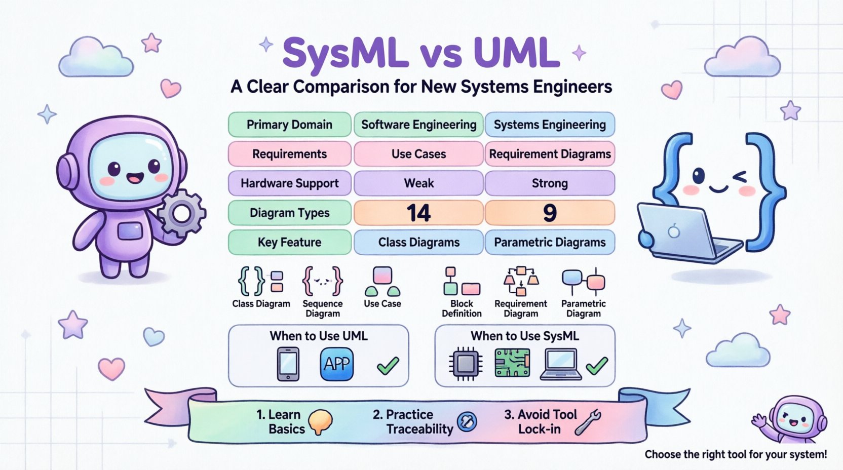
| Primary Domain | Software Engineering | Systems Engineering |
| Origin | Mid-1990s (OMG) | Early 2000s (OMG) |
| Requirements | Limited support (Use Cases) | Dedicated Requirement Diagrams |
| Hardware Modeling | Weak support | Strong support (Blocks) |
| Constraints | Basic OCL | Parametric Diagrams |
| Diagram Count | 14 Types | 9 Types |
| Complexity | High for software | High for system integration |
Understanding these distinctions helps prevent the common mistake of forcing UML into a hardware-heavy systems engineering context where it might not provide the necessary abstraction.
Deep Dive into Diagram Types 📐
The power of a modeling language lies in its diagrammatic capabilities. Let’s examine the specific diagrams available in each language and what they are best used for.
UML Diagram Types
UML offers a broad range of diagrams, categorized into structural and behavioral. For software engineers, these are the standard tools.
- Class Diagram: Shows the static structure of a system, including classes, attributes, and relationships.
- Sequence Diagram: Illustrates how objects interact over time in a specific scenario.
- Use Case Diagram: Describes the functional requirements from the perspective of an actor.
- State Machine Diagram: Represents the different states an object can be in and the transitions between them.
- Activity Diagram: Similar to flowcharts, showing the flow of control or data.
- Component Diagram: Shows the physical components of the system and their interfaces.
- Deployment Diagram: Maps software artifacts onto hardware nodes.
SysML Diagram Types
SysML reduces the complexity of UML by selecting the most relevant diagrams for systems engineering and adding new ones. There are nine specific diagram types in SysML.
- Block Definition Diagram (BDD): Similar to a class diagram, this defines the structure of a system. It focuses on blocks, which represent components, systems, or subsystems, rather than just software classes.
- Internal Block Diagram (IBD): Shows the internal structure of a block, including ports and connectors. This is crucial for defining how parts connect within a system.
- Requirement Diagram: A unique SysML feature. It allows you to capture, manage, and trace requirements. This is a major differentiator from UML.
- Use Case Diagram: Similar to UML, but adapted for system actors and functions rather than just software users.
- Sequence Diagram: Used for defining interactions between blocks or system components.
- Parametric Diagram: Crucial for Systems Engineering. This allows you to define mathematical constraints and equations. It is used to verify if a system meets performance criteria (e.g., weight, power, latency).
- State Machine Diagram: Used to model the behavior of blocks over time.
- Activity Diagram: Used for modeling the flow of work or data.
- Package Diagram: Used to organize model elements.
Modeling Requirements: A Key Differentiator 📝
One of the most significant advantages SysML holds over UML is its approach to requirements. In systems engineering, requirements are the foundation of the design. They define what the system must do.
UML and Requirements
In UML, requirements are typically handled through Use Case Diagrams. A Use Case describes a function or interaction. While you can annotate use cases with requirements, the relationship is loose. There is no formal mechanism to link a specific requirement text to a design element without using notes or stereotypes that are not part of the standard.
SysML and Requirements
SysML treats requirements as first-class citizens. The Requirement Diagram allows you to:
- Define requirements as specific objects with unique identifiers.
- Assign attributes such as priority, status, and type (e.g., functional, performance).
- Create relationships like “satisfies,” “verifies,” “refines,” and “derives.”
This traceability is vital for compliance and verification. If a requirement changes, you can instantly see which design blocks or tests are affected. This level of granularity is often missing in standard UML implementations.
Behavior and Structure: Blocks vs. Classes ⚙️
The concept of a “Block” in SysML is analogous to a “Class” in UML, but the semantics are broader.
The Software View (UML Class)
A UML Class represents a blueprint for objects in a software system. It focuses on data (attributes) and behavior (methods). It assumes a programming language context where inheritance and polymorphism are key concepts.
The Systems View (SysML Block)
A SysML Block is more abstract. A block can represent a software class, a physical part like a sensor, a subsystem like a battery pack, or even a person. Blocks are defined by:
- Part: Parts contained within a block (composition).
- Reference: Connections to blocks outside the current block (aggregation).
- Port: Interfaces through which a block interacts with its environment.
- Flow: The flow of information, energy, or material through the ports.
This distinction is critical. If you are modeling a satellite, a “Block” is the satellite itself, a solar panel, or a thruster. A “Class” would be too narrow, implying only software logic.
Parametric Analysis and Constraints 🔬
Systems engineering often involves trade-offs. How much weight can a structure support? How much power does a system consume? UML is not designed to answer these questions mathematically.
SysML introduces the Parametric Diagram to address this. This diagram allows you to:
- Define equations that model system performance.
- Link physical properties (like mass or voltage) to mathematical variables.
- Run simulations to verify if the design meets the constraints.
For example, you can define a constraint equation for a thermal system. If the variable exceeds a certain threshold, the system is flagged as non-compliant. This capability bridges the gap between high-level design and engineering physics, a gap that UML cannot cross without external tools or custom extensions.
When to Use Which Language? 🤔
Choosing between SysML and UML depends on the nature of the project and the stakeholders involved.
Use UML When:
- The system is primarily software-based.
- The team consists mainly of software developers and architects.
- The focus is on code structure, class relationships, and data flow.
- Integration with hardware is minimal or handled by a separate team.
- You are building a standalone application or service.
Use SysML When:
- The project involves complex hardware-software integration.
- Requirements management is a primary concern.
- Performance, weight, power, and other physical constraints are critical.
- You are practicing Model-Based Systems Engineering (MBSE).
- The system includes non-software elements like mechanical parts, electrical circuits, or human operators.
In many modern projects, you might find yourself using both. For instance, SysML could model the high-level system architecture, while UML is used for the detailed design of the embedded software modules within those systems. However, maintaining consistency between the two requires careful management.
Learning Path for New Engineers 📚
If you are starting your journey in systems engineering, here is a recommended approach to learning these languages.
- Start with the Basics: Understand the concept of a model. What are you trying to represent?
- Learn SysML First (if Systems Engineering): If your role is Systems Engineering, SysML is the native language. Focus on Blocks and Requirements first.
- Understand UML Fundamentals: Even if you use SysML, understanding UML helps because SysML is a profile of UML. You will recognize the syntax.
- Practice Traceability: Learn how to link a requirement to a design element. This is the core value of modeling.
- Study Integration: Look at how hardware and software interfaces are defined in your models.
- Avoid Tool Lock-in: Focus on the concepts, not the specific software interface. The principles remain the same regardless of the modeling tool you use.
Common Pitfalls to Avoid ⚠️
As you begin modeling, several common mistakes can hinder your progress.
- Over-Modeling: Creating diagrams for every single detail before understanding the high-level architecture. Start with the big picture.
- Mixing Languages: Trying to force UML requirements into SysML blocks without understanding the mapping. Keep the domains distinct.
- Ignoring Constraints: In SysML, failing to use Parametric Diagrams means you are missing a key verification step.
- Static Requirements: Treating requirements as text documents rather than model elements. Requirements should be traceable and dynamic.
- Software Bias: Applying software-centric thinking (like inheritance) to hardware systems where composition is more accurate.
The Future of Systems Modeling 🔮
The field of systems engineering is evolving. The adoption of MBSE is increasing across industries including aerospace, automotive, and medical devices. As systems become more interconnected, the need for a unified language that bridges hardware and software grows.
SysML continues to gain traction because it provides the flexibility required for these complex environments. It allows for a single source of truth that stakeholders from different disciplines can access. While UML remains the standard for software development, SysML is becoming the standard for the broader system.
Looking ahead, we may see further integration with data science and artificial intelligence. Models may become more interactive, allowing for automated verification and synthesis. However, the core principles of defining structure, behavior, and requirements will remain the foundation of these technologies.
Final Thoughts on Modeling 🛠️
Choosing between SysML and UML is not just about syntax; it is about the mindset of the engineer. UML invites you to think in terms of objects and software logic. SysML invites you to think in terms of components, interfaces, and physical constraints.
For a new systems engineer, mastering SysML is often the priority. It equips you with the tools to manage complexity in a way that pure software modeling cannot. However, a working knowledge of UML ensures you can communicate effectively with software teams.
The goal is not to memorize every diagram type but to use the right tool to solve the problem at hand. By understanding the strengths and limitations of each language, you can build models that are clear, actionable, and valuable to your team. This clarity is what turns a complex engineering challenge into a manageable design process.
As you move forward, focus on traceability and clarity. Whether you are designing a simple app or a complex vehicle, the ability to visualize and document your system is a critical skill. Keep practicing, keep refining your models, and always prioritize the needs of the system over the elegance of the diagram.

